CAN BUS FD Shield for Raspberry Pi
CAN FD is an extension to the original CAN bus protocol that was specified in ISO 11898-1. Developed in 2011 and released in 2012 by Bosch. The primary difference between the classical CAN (Controller Area Network) and CAN FD is the Flexible Data (FD). Using CAN FD, Electronic Control Unit (ECU)s can dynamically switch to different data-rate and with larger or smaller message sizes. The message payload size has been increased to 64 bytes of data in each CAN message, instead on classic CAN there are only 8-bytes. The CAN FD ID has 29-bits like Extended ID of CAN2.0B. DualCanBus FD Pi V 1.1 is a CAN BUS FD Shield for Raspberry Pi. It is an Open Hardware Design. It has two functionalities: a can bus module and an onboard Real Time clock powered by a 12 mm battery CR1216 (Battery is not included). The CAN BUS FD is based on a couple of MCP2517 SPI controllers and MCP2557 tranceivers. The real time clock is based on DS3231 with internal oscillator I2C controller. It is full compatible with linux too. Using I2C Kernel module, and standard kernel functions, date and hour can be set/get by simple commands. On the bottom side is located an on board battery to guarantee a data autonomy. In chapter hardware there are all informations on principal components, schematics to rebuild and modify RaspBerry PI board. The new board is designed with the Raspberry Hat specification. The connection between Raspberry Pi and MCP2517 is inspired by the project of Seeedstudio , in this way it is possible to use the seeedstudio software installation.
The primary difference between the classical CAN (Controller Area Network) and CAN FD is the Flexible Data (FD). Using CAN FD, Electronic Control Unit (ECU)s can dynamically switch to different data-rate and with larger or smaller message sizes.
The rest of the board is a classical SG board configuration:
- RTC DS3231
- Battery CR1216
- 2 Leds
- Solder jumper for 120 ohm
Considering the heating production or Raspberry Pi 4, we have add a small fan.
Raspberry Boards Compatibility
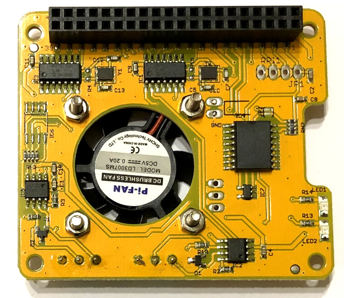
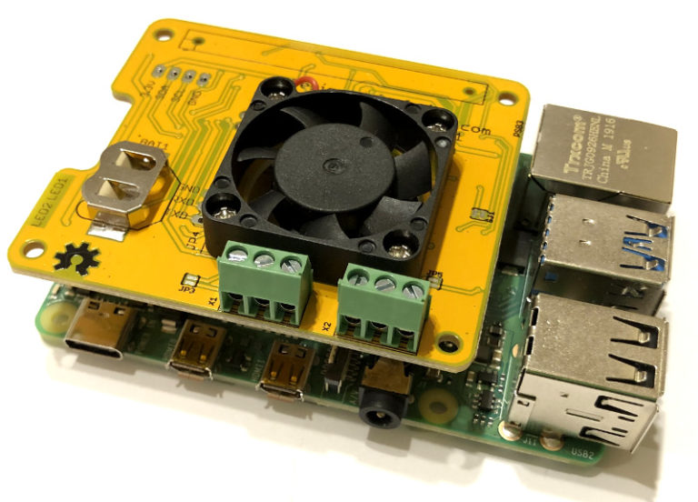
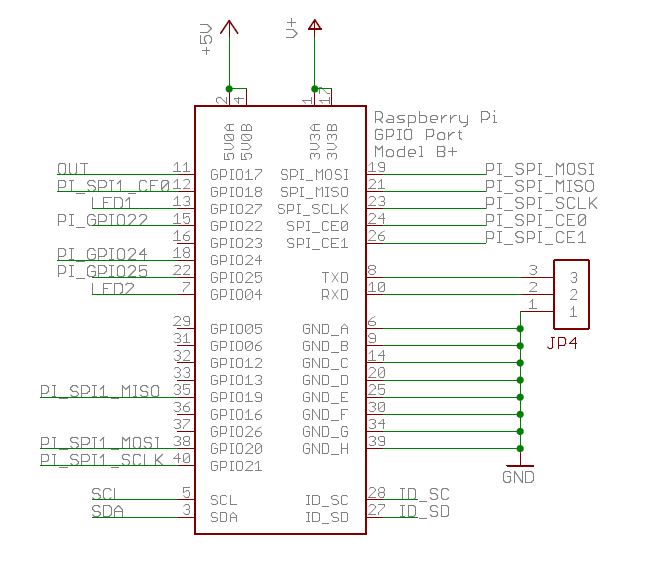
The RPI connector exposes two SPI buses, the SPI0 with CE0 on pin 24 is used for CAN FD Channel 1, instead the SPI 1 with CE0 on pin 12 is used for CAN FD Channel 2. The first MCP2517 uses the GPIO 25 on pin 22 for interrupt, instead the second MCP2517 uses the GPIO 24 on pin 18. The Led 1 is connected on GPIO27 pin 13, instead the Led 2 is connected on GPIO4 pin 7.
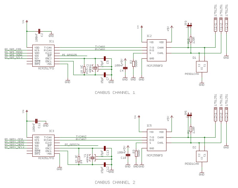
The MCP2517FD supports both, CAN frames in the Classical format (CAN2.0B) and CAN Flexible Data Rate (CAN FD) format, as specified in ISO 11898-1:2015. The MCP2557FD/8FD CAN transceiver family is designed for high-speed CAN FD applications with up to 8 Mbps communication speed. The maximum propagation delay was improved to support longer bus length.The device meets automotive requirements for CAN FD bit rates exceeding 2 Mbps, low quiescent current, electromagnetic compatibility (EMC) and electrostatic discharge (ESD). There are two SMD Jumpers, JP3 for CAN BUS FD Channel 1 and JP5 for CAN BUS FD Channel 2, these jumpers provide the 120 ohm termination for the first and the last device.
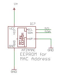
We have add an I2C eeprom AT24MAC for permanent data storing and a preconfigurated MAC.
This board is not compliant with our QUAD CAN ADAPTER.
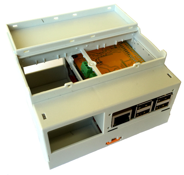
It’s possible to insert the Raspberry with our Can Bus Board into a Phoenix din enclosure (RPI-BC 107,6 DEV-KIT KMGY – 2202874).
Software Test
It is possible to use the seeedstudio software installation.
git clone https://github.com/seeed-Studio/pi-hats
cd pi-hats/CAN-HAT
sudo ./install.sh
sudo reboot
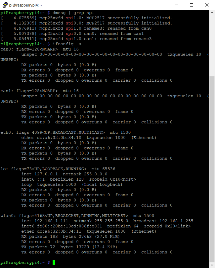
If all the software installation is completed without errors, it is possible to check the installed interface with command ifconfig -a .
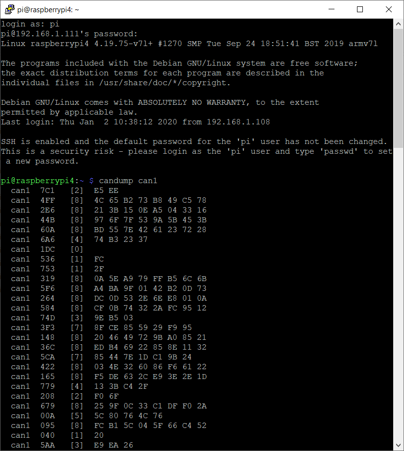
It is possible to generate random CAN FD Message with command cangen. For our test we have used only 1 board, with cangen on can0 and candump on can1
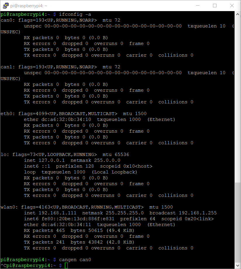
In order to run candump together cansend on the same Raspberry, I have oper two different sessions.
Leave a Reply