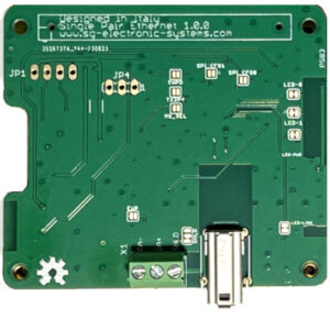
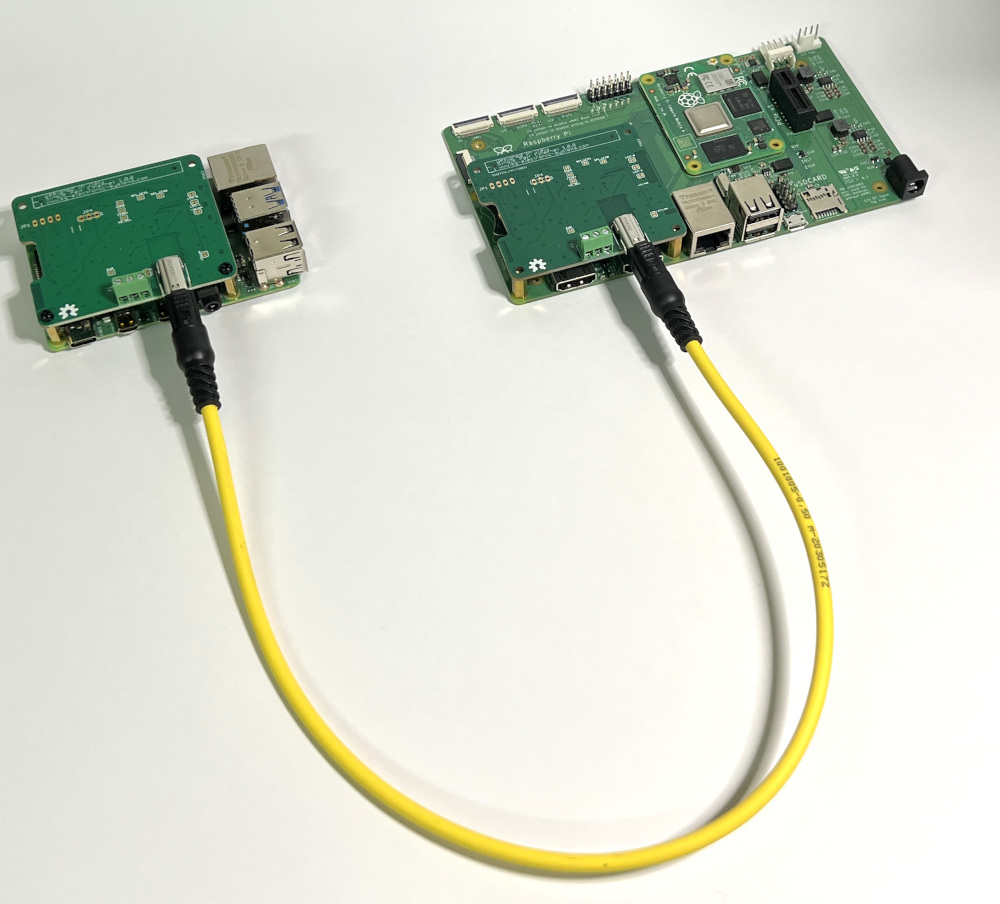
Single Pair Ethernet V1.0.0 Shield for Raspberry Pi
Single Pair Ethernet (SPE) is a technology that enables the transmission of Ethernet data over a single twisted pair of wires, as opposed to the traditional Ethernet which typically uses four pairs of twisted wires. This technology was developed to address the growing demand for connectivity in various industries, especially in scenarios where traditional Ethernet cabling might be impractical due to space, weight, or cost constraints. SPE is designed to provide Ethernet connectivity for devices that don’t require the high bandwidth provided by traditional Ethernet cables and can operate over shorter distances. It’s particularly useful in industrial applications, building automation, automotive systems, and the Internet of Things (IoT) devices, where the data requirements are relatively modest but reliable connectivity is essential.
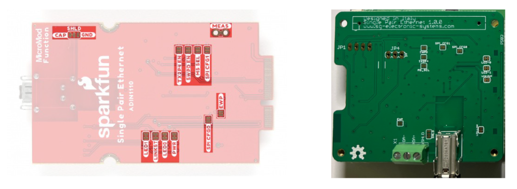
SINGLE PAIR ETHERNET V1.0.0 Shield for Raspberry Pi is an Open Hardware Design. It has two functionalities: a Single Pair Ethernet module and an onboard Real Time clock powered by a 12 mm battery CR1216 (Battery is not included). The SPE is based onADIN1110 SPI controller.
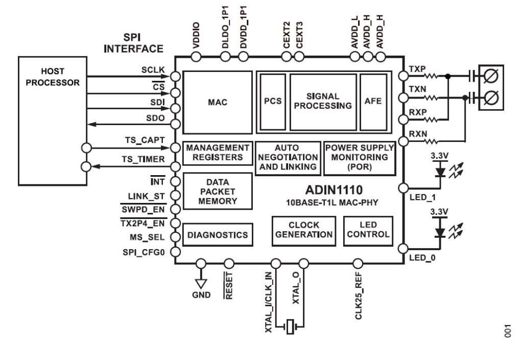
The ADIN1110 is an ultra low power, single port, 10BASE-T1L transceiver design for industrial Ethernet applications and is compliant with the IEEE® 802.3cg-2019™ Ethernet standard for long reach, 10 Mbps single pair Ethernet (SPE). Featuring an integrated media access control (MAC) interface, the ADIN1110 enables direct connectivity with a variety of host controllers via a serial peripheral interface (SPI). This SPI enables the use of lower power processors without an integrated MAC, which provides for the lowest overall system level power consumption. The ADIN1110 is designed for edge node sensors and field instruments deployed in building, factor, and process automation. See ADIN1110 datasheet for a detailed description.
Raspberry Boards Compatibility
It’s possible to order this board on our Shop.
The board proposed in this document is a fusion of Sparkfun COM-19038 ADIN1110 Board schematic and AnalogDevice EVAL-ADIN1110. There are same minor differences between the two projects:
- SPE Connector
- Tranformer
- ESD/Surge protection
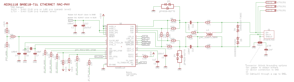
But we have maintained both the SPE connectors :AH IP20 produced by Harting and 3-WAY Phoneix Contact 1803280
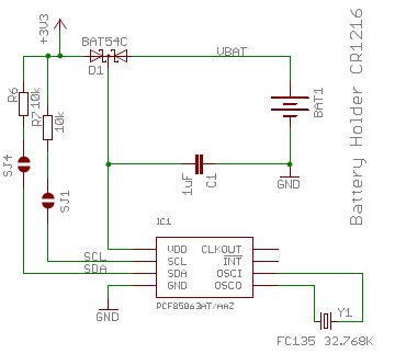
Considering that Raspberry PI has no RTC, we have ad one.
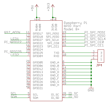
On Raspberry connector there are the following used pins/peripherals:
- SPI0
- I2C
- ADIN1110 reset on GPIO17
- ADIN1110 interrupt on GPIO22
- LED1 on GPIO27
- LED2 on GPIO04
The solder jumpers are the same present on COM-19038.
DESIGN FILES
Software configuration
For software configuration follow this link.
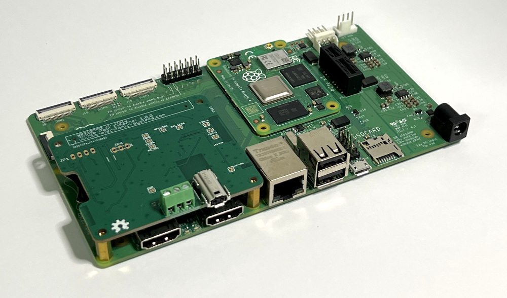
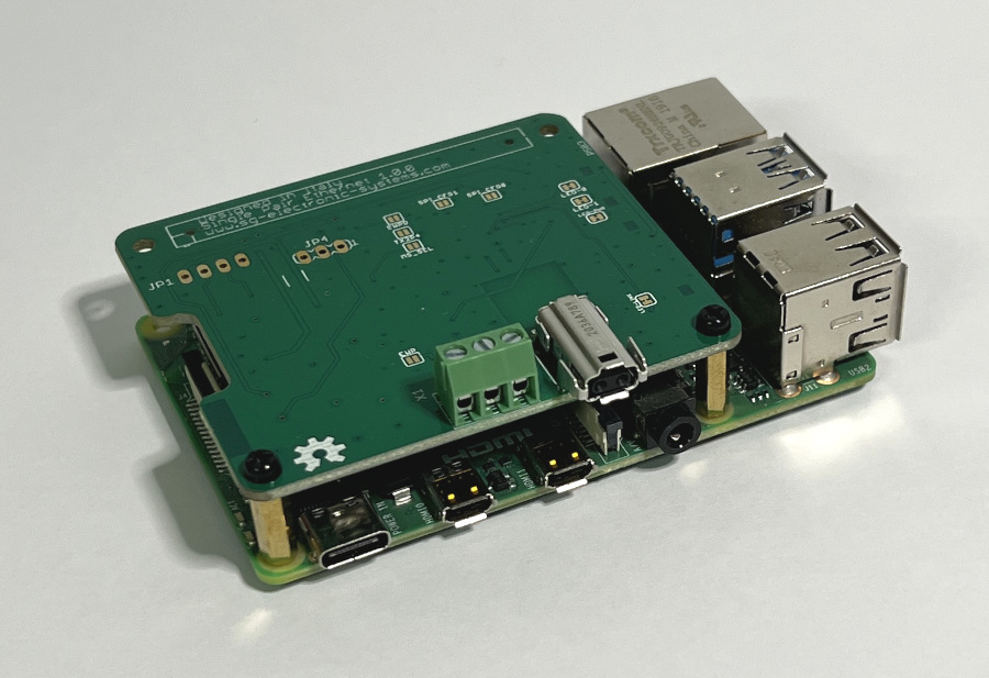
Board installation
It is possible to install all our boards both on Raspberry Pi or CM4IO carrier, but it’s always suggested to use standoff M2.5 x 10 mm
It’s possible to insert the Raspberry with our Can Bus Board into a Phoenix din enclosure (RPI-BC 107,6 DEV-KIT KMGY – 2202874).
DISCLAIMER
This project is Open Source, you can able to download both source and production files.
Distributed as-is, no warranty is given.
Leave a Reply