Dual Can PICO V1.0
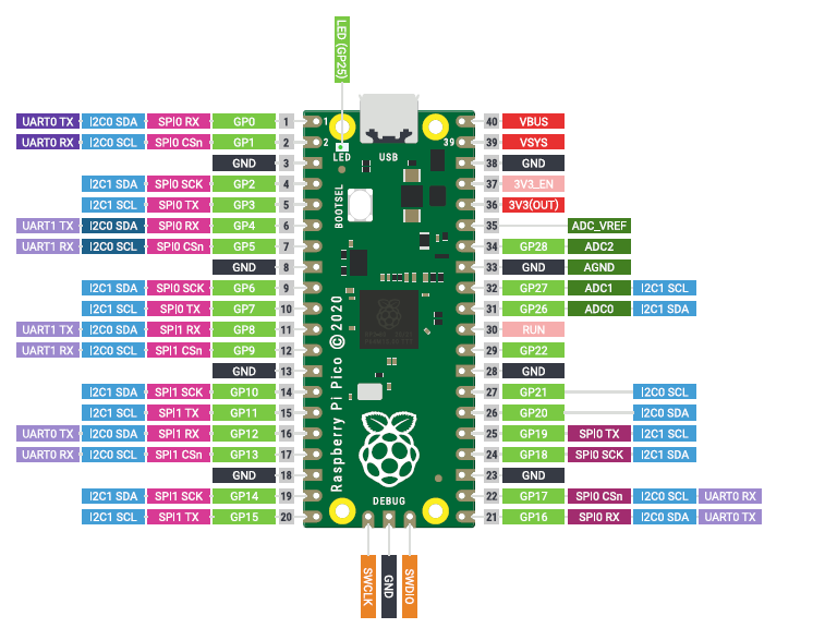
Raspberry PICO is an interesting extension of Raspberry family. It is based on RP2040 microcontroller, a dual-core Arm Cortex-M0+ processor, flexible clock running up to 133 MHz 264kB on-chip SRAM 2MB on-board QSPI flash, 26 GPIO pins, including 3 analogue inputs.
There are the following peripherals:
- 2 × UART
- 2 × SPI controllers
- 2 × I2C controllers
- 16 × PWM channels
- 1 × USB 1.1 controller and PHY, with host and device support
- 8 × PIO state machines
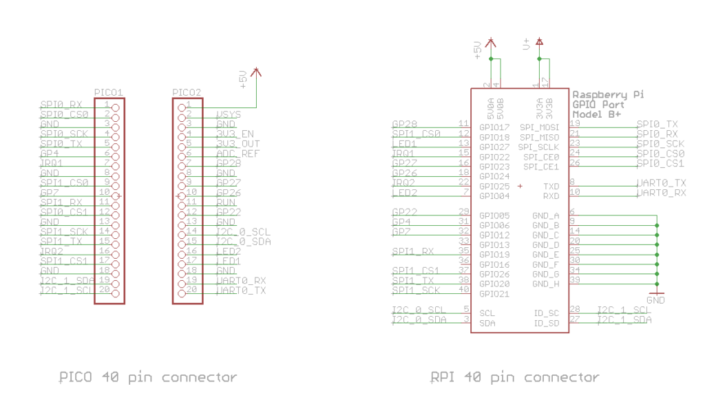
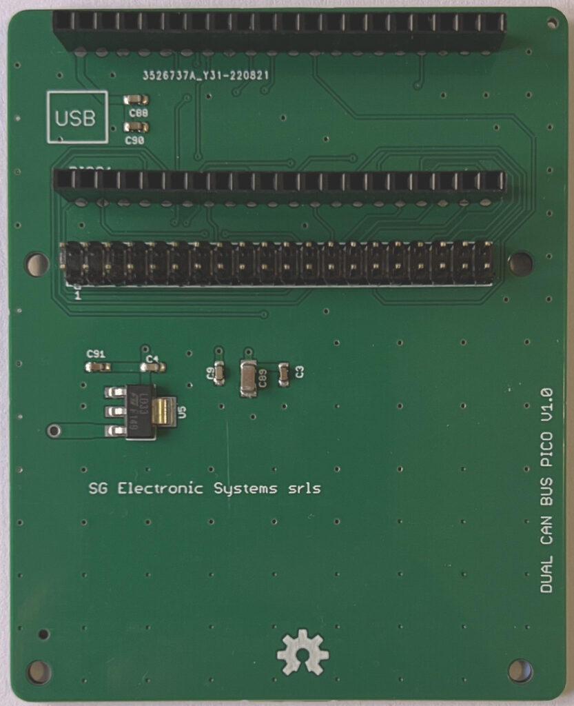
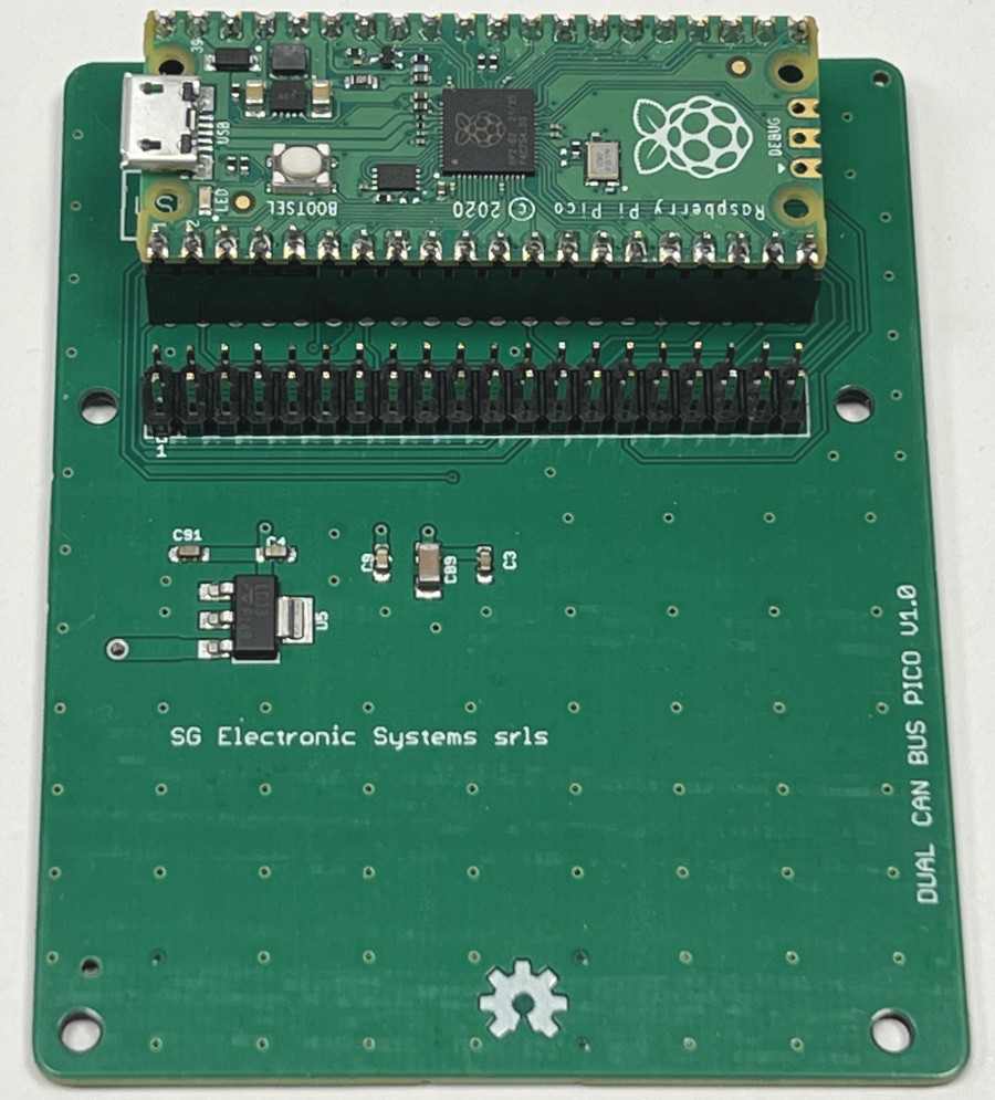
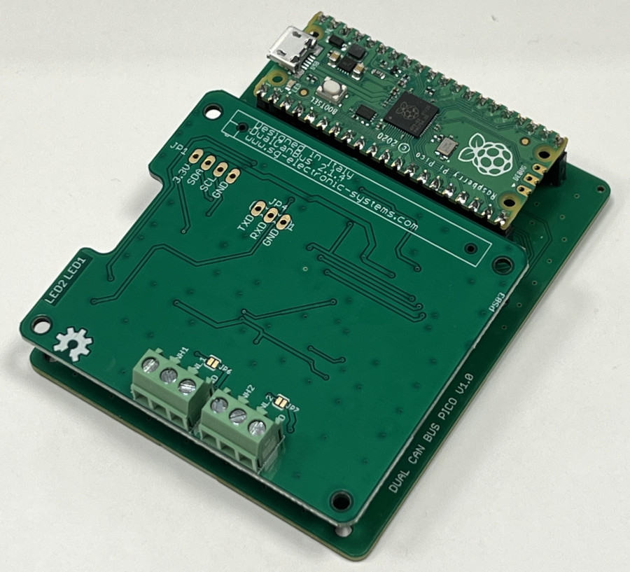
Dual Can Bus PICO is an adapter to use our Can Bus Board with PICO. The idea is to connect all the 40 pins connector of Raspberry to the new board.
Buy on our shop
Hardware Files
All our projects are open hardware, these are the production files:
Software Configuration
An embedded system is very interesting for open hardware community only if it is well supported with free IDE and library. There are two IDE software to develop firmware: Arduino IDE and Visual Studio Code.
For stability and simplicity we prefer to use Arduino IDE. The RP2040 core used in this example is developed by Earle Philhower. Use the following steps to prepare the IDE:
- Open IDE
- Click on File
- Click on Preference
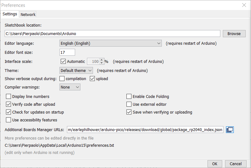
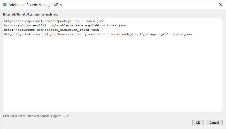
- Click on Additional Board Manager URLs and add this link https://github.com/earlephilhower/arduino-pico/releases/download/global/package_rp2040_index.json
- Click OK
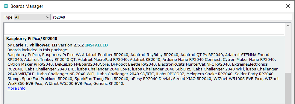
- Click on Tools
- Click on Board Manager
- Install RP2040 core
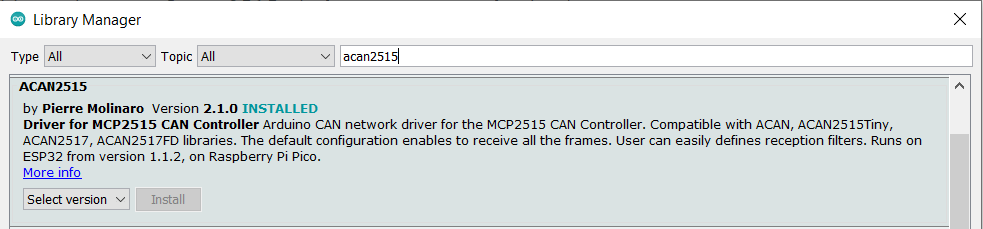
- Install ACAN2515 of Pierre Molinaro
- Click on Sketch
- Include Library
- Manage Libraries
- Select Raspberry Pi PICO
Dual Can Bus Sketch
Download PicoDualCan_V1.0.ino
There are two kind of RTC for our boards, the DS3231 and PCF85063. Verify the installed RTC on your board and enabled the correct #define.
//——————————————————————————————————————————————————————————————————————————————
//  SG Electronic Systems srls
//  This Example is derived by
//  ACAN2515 Demo in loopback mode, for the Raspberry Pi Pico
//  Thanks to Duncan Greenwood for providing this sample sketch
//——————————————————————————————————————————————————————————————————————————————
// Pico Adapter Pinout
// SPI0_SCK         2
// SPI0_MISO        0
// SPI0_MOSI        3
// SPI0_CS0         1     CAN0
// SPI0_CS1         9     CAN1
// MCP2515_INT1     4     CAN0
// MCP2515_INT2     12    CAN1
// SPI1_SCK         10
// SPI1_MISO        8
// SPI1_MOSI        11
// SPI1_CS0         6
// SPI1_CS1         13
// I2C0_SDA         20    RTC
// I2C0_SCL         21    RTC
// I2C1_SDA         14
// I2C1_SCL         15
// LED1             18
// LED2             19
// UART0_RX         17
// UART0_TX         16
#ifndef ARDUINO_ARCH_RP2040
#error "Select a Raspberry Pi Pico board"
#endif
#define LED1  18
#define LED2  19
#define LED
#define CAN0
#define CAN1
#define RTC
#define RTC_DS3231
//#define RTC_PCF85063
//——————————————————————————————————————————————————————————————————————————————
#include <Wire.h>
#ifdef RTC_DS3231
#include "DS3231.h"
#endif
#ifdef RTC_PCF85063
#include "PCF85063TP.h"
#endif
#include <ACAN2515.h>
//——————————————————————————————————————————————————————————————————————————————
// The Pico has two SPI peripherals, SPI and SPI1. Either (or both) can be used.
// The are no default pin assignments so they must be set explicitly.
// Testing was done with Earle Philhower's arduino-pico core:
// https://github.com/earlephilhower/arduino-pico
//——————————————————————————————————————————————————————————————————————————————
static const byte SPI0_SCK  = 2 ; // SCK input of MCP2515
static const byte SPI0_MOSI = 3 ; // SDI input of MCP2515
static const byte SPI0_MISO = 0 ; // SDO output of MCP2515
static const byte SPI0_CS0  = 1 ;  // CS input of MCP2515 1
static const byte SPI0_CS1  = 9 ;  // CS input of MCP2515 (2
static const byte I2C0_SDA  = 20 ;
static const byte I2C0_SCL  = 21 ;
#ifdef CAN0
static const byte MCP2515_INT0 = 4 ;  // INT output of MCP2515 (adapt to your design)
ACAN2515 can0 (SPI0_CS0, SPI, MCP2515_INT0) ;
#endif
#ifdef CAN1
static const byte MCP2515_INT1 = 12 ;  // INT output of MCP2515 (adapt to your design)
ACAN2515 can1 (SPI0_CS1, SPI, MCP2515_INT1) ;
#endif
#ifdef RTC_DS3231
#define DS3231_I2C_ADDRESS 0x68
#endif
#ifdef RTC_PCF85063
PCD85063TP clock;//define a object of PCD85063TP class
#endif
static const uint32_t QUARTZ_FREQUENCY = 16UL * 1000UL * 1000UL ; // 16 MHz
static uint32_t gBlinkLedDate0 = 0 ;
static uint32_t gReceivedFrameCount0 = 0 ;
static uint32_t gSentFrameCount0 = 0 ;
static uint32_t gBlinkLedDate1 = 0 ;
static uint32_t gReceivedFrameCount1 = 0 ;
static uint32_t gSentFrameCount1 = 0 ;
//——————————————————————————————————————————————————————————————————————————————
//   SETUP
//——————————————————————————————————————————————————————————————————————————————
void setup () {
  #ifdef LED
  pinMode (LED1, OUTPUT) ;  // For CAN0
  digitalWrite (LED1, HIGH) ;
  pinMode (LED2, OUTPUT) ;  // For CAN1
  digitalWrite (LED2, HIGH) ;
  #else   //--- Switch on builtin led
  pinMode (LED_BUILTIN, OUTPUT) ;
  digitalWrite (LED_BUILTIN, HIGH) ;
  #endif
  //--- Start serial
  Serial.begin (115200) ;

  //--- Wait for serial (blink led at 10 Hz during waiting)
  while (!Serial) {
    delay (50) ;
    #ifdef LED
    digitalWrite (LED1, !digitalRead (LED1)) ;
    delay (50) ;
    digitalWrite (LED2, !digitalRead (LED2)) ;
    #else
    digitalWrite (LED_BUILTIN, !digitalRead (LED_BUILTIN)) ;
    #endif
  }
  //--- There are no default SPI pins so they must be explicitly assigned
  SPI.setSCK(SPI0_SCK);
  SPI.setTX(SPI0_MOSI);
  SPI.setRX(SPI0_MISO);
  //--- Begin SPI
  SPI.begin () ;
  #ifdef CAN0
  //--- Configure ACAN2515
  Serial.println ("Configure ACAN2515 CAN0") ;
  ACAN2515Settings settings0 (QUARTZ_FREQUENCY, 125UL * 1000UL) ; // CAN bit rate 125 kb/s
  settings0.mRequestedMode = ACAN2515Settings::NormalMode  ; // Select NormalMode  mode
  const uint16_t errorCode0 = can0.begin (settings0, [] { can0.isr () ; }) ;
  if (errorCode0 == 0) {
    Serial.print ("Bit Rate prescaler: ") ;
    Serial.println (settings0.mBitRatePrescaler) ;
    Serial.print ("Propagation Segment: ") ;
    Serial.println (settings0.mPropagationSegment) ;
    Serial.print ("Phase segment 1: ") ;
    Serial.println (settings0.mPhaseSegment1) ;
    Serial.print ("Phase segment 2: ") ;
    Serial.println (settings0.mPhaseSegment2) ;
    Serial.print ("SJW: ") ;
    Serial.println (settings0.mSJW) ;
    Serial.print ("Triple Sampling: ") ;
    Serial.println (settings0.mTripleSampling ? "yes" : "no") ;
    Serial.print ("Actual bit rate: ") ;
    Serial.print (settings0.actualBitRate ()) ;
    Serial.println (" bit/s") ;
    Serial.print ("Exact bit rate ? ") ;
    Serial.println (settings0.exactBitRate () ? "yes" : "no") ;
    Serial.print ("Sample point: ") ;
    Serial.print (settings0.samplePointFromBitStart ()) ;
    Serial.println ("%") ;
  } else {
    Serial.print ("Configuration 0 error 0x") ;
    Serial.println (errorCode0, HEX) ;
  }
  #endif
  #ifdef CAN1
    //--- There are no default SPI pins so they must be explicitly assigned
  //--- Configure ACAN2515 CAN1
  Serial.println ("Configure ACAN2515 CAN1") ;
  ACAN2515Settings settings1 (QUARTZ_FREQUENCY, 125UL * 1000UL) ; // can1 bit rate 125 kb/s
  settings1.mRequestedMode = ACAN2515Settings::NormalMode  ; // Select NormalMode  mode
  const uint16_t errorCode1 = can1.begin (settings1, [] { can1.isr () ; }) ;
  if (errorCode1 == 0) {
    Serial.print ("Bit Rate prescaler: ") ;
    Serial.println (settings1.mBitRatePrescaler) ;
    Serial.print ("Propagation Segment: ") ;
    Serial.println (settings1.mPropagationSegment) ;
    Serial.print ("Phase segment 1: ") ;
    Serial.println (settings1.mPhaseSegment1) ;
    Serial.print ("Phase segment 2: ") ;
    Serial.println (settings1.mPhaseSegment2) ;
    Serial.print ("SJW: ") ;
    Serial.println (settings1.mSJW) ;
    Serial.print ("Triple Sampling: ") ;
    Serial.println (settings1.mTripleSampling ? "yes" : "no") ;
    Serial.print ("Actual bit rate: ") ;
    Serial.print (settings1.actualBitRate ()) ;
    Serial.println (" bit/s") ;
    Serial.print ("Exact bit rate ? ") ;
    Serial.println (settings1.exactBitRate () ? "yes" : "no") ;
    Serial.print ("Sample point: ") ;
    Serial.print (settings1.samplePointFromBitStart ()) ;
    Serial.println ("%") ;
  }else{
    Serial.print ("Configuration 1 error 0x") ;
    Serial.println (errorCode1, HEX) ;
  }
  #endif
  #ifdef RTC
  Wire.setSDA(I2C0_SDA);
  Wire.setSCL(I2C0_SCL);
  Wire.begin();
  #endif
  #ifdef RTC_PCF85063
  clock.begin();
  //clock.setcalibration(1, 32767.2);  // Setting offset by clock frequency
  uint8_t ret = clock.calibratBySeconds(0, -0.000041);
  Serial.print("offset value: ");
  Serial.print("0x");
  Serial.println(ret, HEX);
  #endif
}
#ifdef RTC_PCF85063
void displayTime()
{
  char minute, hour, dayOfWeek, dayOfMonth, month, year, second;
  clock.getTime();
  second = clock.second;
  minute = clock.minute;
  hour = clock.hour;
  dayOfWeek = clock.dayOfWeek;
  dayOfMonth = clock.dayOfMonth;
  month = clock.month;
  year = clock.year+2000;
  // send it to the serial monitor
  Serial.print(hour, DEC);
  // convert the byte variable to a decimal number when displayed
  Serial.print(":");
  if (minute<10)
  {
    Serial.print("0");
  }
  Serial.print(minute, DEC);
  Serial.print(":");
  if (second<10)
  {
    Serial.print("0");
  }
  Serial.print(second, DEC);
  Serial.print(" ");
  Serial.print(dayOfMonth, DEC);
  Serial.print("/");
  Serial.print(month, DEC);
  Serial.print("/");
  Serial.print(year, DEC);
  Serial.print(" Day of week: ");
  switch(dayOfWeek){
  case 1:{
    Serial.println("Sunday");
    }
    break;
  case 2:{
    Serial.println("Monday");
  }
    break;
  case 3:{
    Serial.println("Tuesday");
  }
    break;
  case 4:{
    Serial.println("Wednesday");
  }
    break;
  case 5:{
    Serial.println("Thursday");
    }
    break;
  case 6:{
    Serial.println("Friday");
  }
    break;
  case 7:{
    Serial.println("Saturday");
  }
    break;
    default:
  Serial.println();
  break;
  }
}
#endif
#ifdef RTC_DS3231
// Convert normal decimal numbers to binary coded decimal
byte decToBcd(byte val)
{
  return( (val/10*16) + (val%10) );
}
// Convert binary coded decimal to normal decimal numbers
byte bcdToDec(byte val)
{
  return( (val/16*10) + (val%16) );
}
void setDS3231time(byte second, byte minute, byte hour, byte dayOfWeek, byte
dayOfMonth, byte month, byte year)
{
  // sets time and date data to DS3231
  Wire.beginTransmission(DS3231_I2C_ADDRESS);
  Wire.write(0); // set next input to start at the seconds register
  Wire.write(decToBcd(second)); // set seconds
  Wire.write(decToBcd(minute)); // set minutes
  Wire.write(decToBcd(hour)); // set hours
  Wire.write(decToBcd(dayOfWeek)); // set day of week (1=Sunday, 7=Saturday)
  Wire.write(decToBcd(dayOfMonth)); // set date (1 to 31)
  Wire.write(decToBcd(month)); // set month
  Wire.write(decToBcd(year)); // set year (0 to 99)
  Wire.endTransmission();
}
void readDS3231time(byte *second,
byte *minute,
byte *hour,
byte *dayOfWeek,
byte *dayOfMonth,
byte *month,
byte *year)
{
  Wire.beginTransmission(DS3231_I2C_ADDRESS);
  Wire.write(0); // set DS3231 register pointer to 00h
  Wire.endTransmission();
  Wire.requestFrom(DS3231_I2C_ADDRESS, 7);
  // request seven bytes of data from DS3231 starting from register 00h
  *second = bcdToDec(Wire.read() & 0x7f);
  *minute = bcdToDec(Wire.read());
  *hour = bcdToDec(Wire.read() & 0x3f);
  *dayOfWeek = bcdToDec(Wire.read());
  *dayOfMonth = bcdToDec(Wire.read());
  *month = bcdToDec(Wire.read());
  *year = bcdToDec(Wire.read());
}
void displayTime()
{
  byte  minute, hour, dayOfWeek, dayOfMonth, month, year, second;
  // retrieve data from DS3231
  readDS3231time(&second, &minute, &hour, &dayOfWeek, &dayOfMonth, &month,
  &year);
  // send it to the serial monitor
  Serial.print(hour, DEC);
  // convert the byte variable to a decimal number when displayed
  Serial.print(":");
  if (minute<10)
  {
    Serial.print("0");
  }
  Serial.print(minute, DEC);
  Serial.print(":");
  if (second<10)
  {
    Serial.print("0");
  }
  Serial.print(second, DEC);
  Serial.print(" ");
  Serial.print(dayOfMonth, DEC);
  Serial.print("/");
  Serial.print(month, DEC);
  Serial.print("/");
  Serial.print(year, DEC);
  Serial.print(" Day of week: ");
  switch(dayOfWeek){
  case 1:{
    Serial.println("Sunday");
    }
    break;
  case 2:{
    Serial.println("Monday");
  }
    break;
  case 3:{
    Serial.println("Tuesday");
  }
    break;
  case 4:{
    Serial.println("Wednesday");
  }
    break;
  case 5:{
    Serial.println("Thursday");
    }
    break;
  case 6:{
    Serial.println("Friday");
  }
    break;
  case 7:{
    Serial.println("Saturday");
  }
    break;
  }

}
#endif
void loop () {
  CANMessage frame0 ;
  CANMessage frame1 ;
  CANMessage frame_read ;
  can0.poll () ;
  can1.poll () ;
  frame0.id =  0x010 ;
  frame0.len =  8 ;
  frame0.data[0] = 10;
  frame0.data[1] = 2;
  frame0.data[2] = 3;
  frame0.data[3] = 4;
  frame0.data[4] = 5;
  frame0.data[5] = 6;
  frame0.data[6] = 7;
  frame0.data[7] = 8;
  frame1.id =  0x002 ;
  frame1.len =  8 ;
  frame1.data[0] = 11;
  frame1.data[1] = 12;
  frame1.data[2] = 13;
  frame1.data[3] = 14;
  frame1.data[4] = 15;
  frame1.data[5] = 16;
  frame1.data[6] = 17;
  frame1.data[7] = 18;
  int len = 0;
  #ifdef CAN0
  // CAN0 loop
  if (gBlinkLedDate0 < millis ()) {
    gBlinkLedDate0 += 2000 ;
    digitalWrite (LED1, !digitalRead (LED1)) ;
    const bool ok0 = can0.tryToSend (frame0) ;
    if (ok0) {
      gSentFrameCount0 += 1 ;
      Serial.print ("Sent 0: ") ;
      Serial.println (gSentFrameCount0) ;
    } else {
      Serial.println ("Send failure 0") ;
    }
  }
  if (can0.available ()) {
    can0.receive (frame_read) ;
    gReceivedFrameCount0 ++ ;
    Serial.print ("CAN0 Received : ") ;
    Serial.print (gReceivedFrameCount0) ;
	Serial.print (" Id: ") ;
	len = frame_read.len;
    Serial.print (frame_read.id) ;
	Serial.print (" Len: ") ;
    Serial.print (len) ;
	Serial.print (" Data: ") ;
	for(int i = 0; i<len; i++)    // print the data
	{
		Serial.print(frame_read.data[i]);
		Serial.print(" ");
	}
	Serial.println();
  }
  #endif
  #ifdef CAN1
  // CAN1 loop
  if (gBlinkLedDate1 < millis ()) {
    gBlinkLedDate1 += 1000 ;
    digitalWrite (LED2, !digitalRead (LED2)) ;
    const bool ok1 = can1.tryToSend (frame1) ;
    if (ok1) {
      gSentFrameCount1 += 1 ;
      Serial.print ("Sent 1: ") ;
      Serial.println (gSentFrameCount1) ;
    } else {
      Serial.println ("Send failure 1") ;
    }
  }
  if (can1.available ()) {
    can1.receive (frame_read) ;
    gReceivedFrameCount1 ++ ;
    Serial.print ("CAN 1 Received: ") ;
    Serial.print (gReceivedFrameCount1) ;
  	Serial.print (" Id: ") ;
  	len = frame_read.len;
    Serial.print (frame_read.id) ;
	  Serial.print (" Len: ") ;
    Serial.print (len) ;
  	Serial.print (" Data: ") ;
  	for(int i = 0; i<len; i++)    // print the data
  	{
  		Serial.print(frame_read.data[i]);
  		Serial.print(" ");
  	}
	  Serial.println();
  }
  #endif
  #ifdef RTC
   delay(500);
   displayTime();
  #endif
}
//——————————————————————————————————————————————————————————————————————————————
Leave a Reply