Lora Shield
Lora Shield PI V 2.3
Lora Shield PI V 2.3 is the new version of our Lora board. The main different is on antennas connectors, the new board mounts a couple of U.FL instead of SMA.
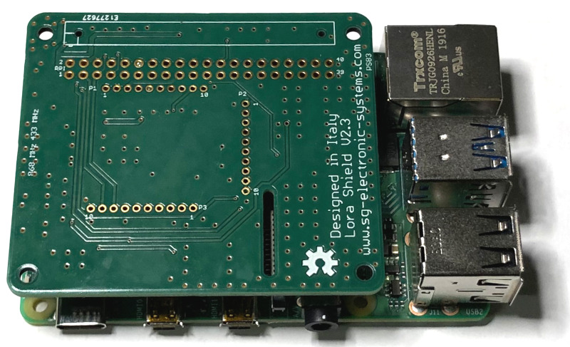
Lora Shield V 2.3 on Raspberry Pi 4
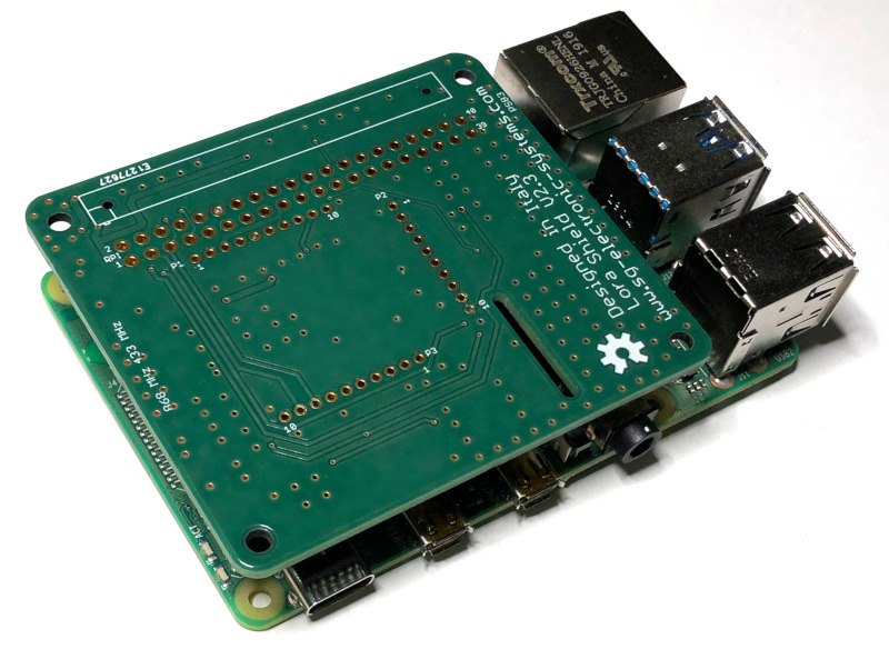
Lora Shield V 2.3 bottom view
Lora Shield PI V 2.2
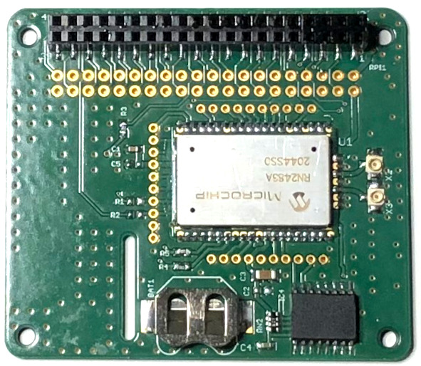
The Lora is based on RN2483 an uart RF module. Lora Shield PI V 2.2 is an extension board for RaspBerry Pi. It is an Open Hardware Design. It has two functionalities: a dual band Lora module and an on board Real Time clock powered by a 12 mm battery CR1216 (Battery is not included). In the following figure is shown the Board Top View. Microchip’s RN2483 Low-Power Long Range LoRa Technology Transceiver module provides an easy to use, low-power solution for long range wireless data transmission. The advanced command interface offers rapid time to market. The RN2483 module complies with the LoRaWAN Class A protocol specifications. It integrates RF, a baseband controller, command Application Programming Interface (API) processor, making it a complete long range solution.
Raspberry Boards Compatibility
It’s possible to order this board on our Shop.
RF Performance declared on datasheet:
- Low-Power Long Range Transceiver Operating in the 433 MHz and 868 MHz Frequency Bands
- High Receiver Sensitivity: Down to -146 dBm
- TX Power: Adjustable up to +14 dBm high Efficiency PA
- FSK, GFSK, and LoRa Technology Modulation
- IIP3 = -11 dBm
- Up to 15 km Coverage at Suburban and up to 5 km Coverage at Urban Area
Lora Shield PI 2.2 is composed by two blocks: one Lora Modules RN2483 U1 shown in and a Real Time Clock. The RN2483 is a stand-alone LORA Module controller with a standard UART interface.
U1 is connected on UART :
- UART RX from PIN 8 TXD
- UART TX from PIN 10 RXD
- RST from GPIO25
- CTS from GPIO17 (With 0 Ω )
- RTS from GPIO16 (With 0 Ω )
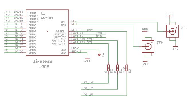
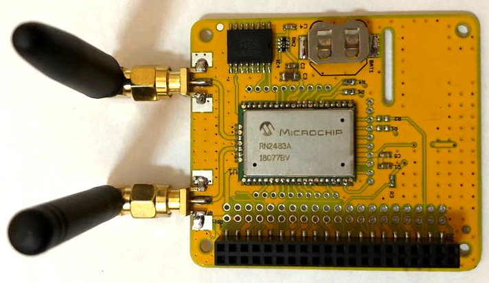
It is important don’t switch the antennas, connector RFL (RF LOW) is for 433Mhz antenna, instead the RFH (RF High) is for 868 Mhz.
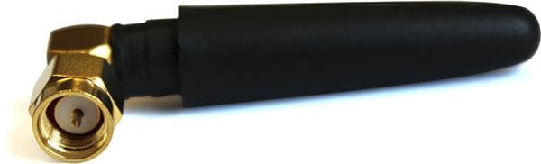
Antenna 433MHz
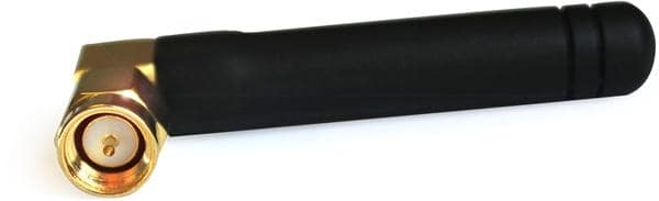
Antenna 868-915 MHz
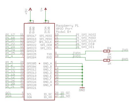
Raspberry connector
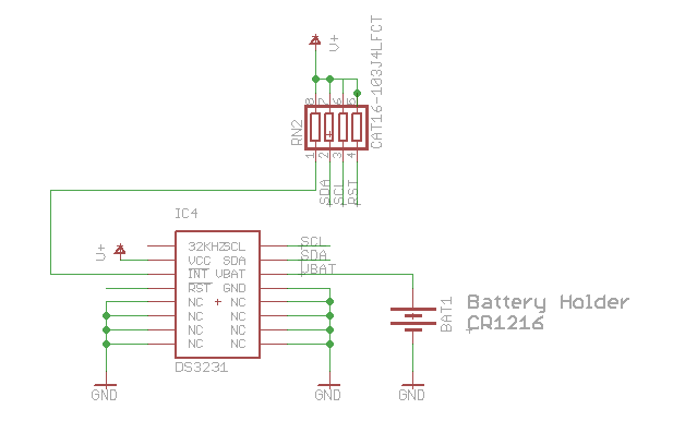
RTC DS3231
Software configuration
As an example to understand the software configuration and the communications of Lora Shield board, the demo scripts are provided in python. To download the python scripts. There are two main python scripts: “receiver.py” and “sender.py”.You can change and adapt the two scripts for your custom application. Parameters and settings of the module are very well detailed in the scripts. For fast test of Lora Shield boards, you can simply use the two standard scripts without any modifications. To use the standard scripts , you have to decide which Lora Shield board is a receiver and which one is a transmitter. Also you have to decide whether you want communicate in 433MHz band or 868MHz band. You have to set the same frequency on both receiver and transmitter. To set the frequency on the receiver board, edit the “receiver.py” script with the command:
pi@raspberrypi ~ $ sudo nano receiver.py
Go to the line where the frequency is set, then set your operating frequency and comment the frequency which is not used as specified below:
# decimal representing the frequency,
# from 433000000 to 434800000 or from 863000000 to 870000000, in Hz.
#print(’cmd> radio set freq 868100000’)
#ser.write(b’radio set freq 868100000\r\n’)
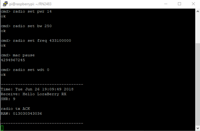
print(’cmd> radio set freq 433100000’)
ser.write(b’radio set freq 433100000\r\n’)
To set the frequency on the transmitter board, edit the “sender.py” script with the command:
pi@raspberrypi ~ $ sudo nano sender.py
Go to the line where the frequency is set, then set your operating frequency and comment the frequency which is not used as specified below:
# decimal representing the frequency,
# from 433000000 to 434800000 or from 863000000 to 870000000, in Hz.
#print(’cmd> radio set freq 868100000’)
#ser.write(b’radio set freq 868100000\r\n’)
print(’cmd> radio set freq 433100000’)
ser.write(b’radio set freq 433100000\r\n’)
After this setting you can run the two scripts on receiver and transmitter board.
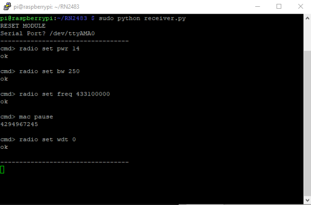
Run the “receiver.py” script on the receiver board with this command:
pi@raspberrypi ~ $ sudo python receiver.py
After running the script set the serial com: “/dev/ttyAMA0”
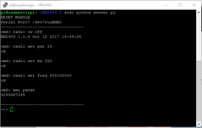
Run the “sender.py” script on the sender board with this command:
pi@raspberrypi ~ $ sudo python sender.py
After running the script set the serial com: “/dev/ttyAMA0”
Data on transmitter
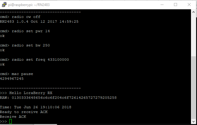
Data on receiver
Leave a Reply