CAN BUS FD V1.4 Shield for Raspberry Pi
CAN FD is an extension to the original CAN bus protocol that was specified in ISO 11898-1. Developed in 2011 and released in 2012 by Bosch. The primary difference between the classical CAN (Controller Area Network) and CAN FD is the Flexible Data (FD). Using CAN FD, Electronic Control Unit (ECU)s can dynamically switch to different data-rate and with larger or smaller message sizes. The message payload size has been increased to 64 bytes of data in each CAN message, instead on classic CAN there are only 8-bytes. The CAN FD ID has 29-bits like Extended ID of CAN2.0B. DualCanBus FD Pi V 1.4 is a CAN BUS FD Shield for Raspberry Pi. It is an Open Hardware Design. It has two functionalities: a can bus module and an onboard Real Time clock powered by a 12 mm battery CR1216 (Battery is not included). The CAN BUS FD is based on a couple of MCP2518FD SPI controllers and MCP2558FD transceivers. The real time clock is based on PCF85063 I2C controller. This is the same RTC of official carrier CM4IO. It is full compatible with linux too. Using I2C Kernel module, and standard kernel functions, date and hour can be set/get by simple commands. On the bottom side is located an on board battery to guarantee a data autonomy. In chapter hardware there are all informations on principal components, schematics to rebuild and modify RaspBerry PI board. The connection between Raspberry Pi and MCP2518FD is inspired by the project of Seeedstudio , in this way it is possible to use the seeedstudio software installation.
The primary difference between the classical CAN (Controller Area Network) and CAN FD is the Flexible Data (FD). Using CAN FD, Electronic Control Unit (ECU)s can dynamically switch to different data-rate and with larger or smaller message sizes.
The rest of the board is a classical SG board configuration:
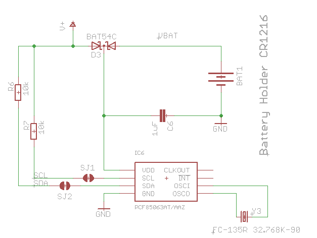
- RTC PCF85063
- Battery CR1216
- 2 Leds
- Solder jumper for 120 ohm
In chapter hardware there are all informations on principal components, schematics to rebuild and modify Raspberry PI board.
Raspberry Boards Compatibility
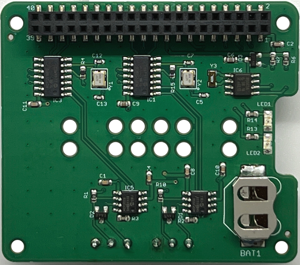
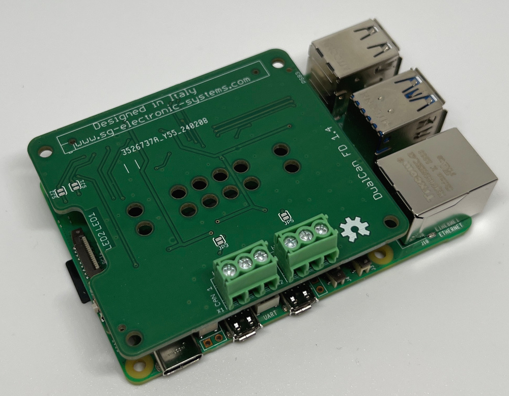
DualCan FD V1.4 Top view
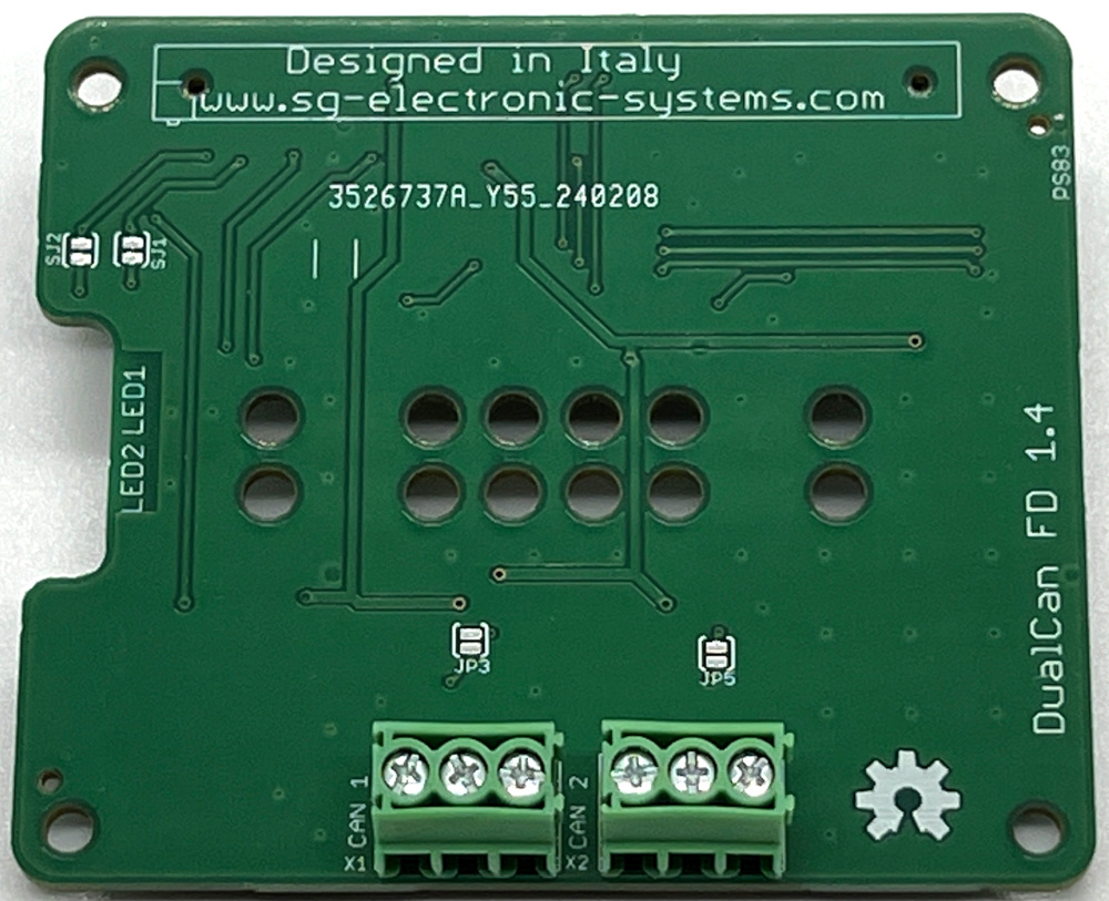
DualCan FD V1.4 Bottom view
It’s possible to order this board on our Shop.
The RPI connector exposes two SPI slave select pins, SPI CE0 on pin 24 and SPI CE1 on pin 26. The first is used for MCP2518FD channel 1 and the second for MCP2518FD channel 2. The same situation is present for the interrupt pins, the first is connected on GPIO25 (pin 22) and the second on GPIO24 (pin 18) .
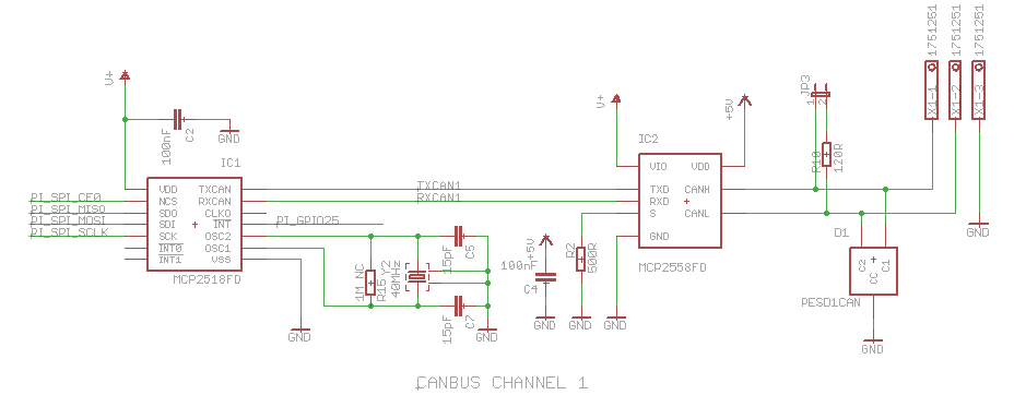
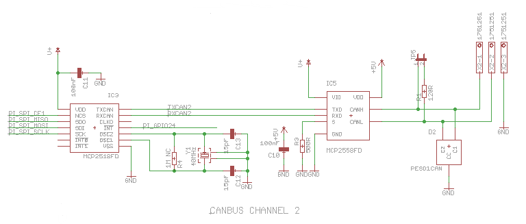
DualCan FD V 1.4 is composed by twoblocks: a couple of CanBus transceiver and a Real Time Clock. MCP2518FD is a stand alone SPI canbus controller full integrated in linux kernel. At the start, the driver was implemented as a block device. Recently it is assumed to be a network module into the kernel. It is supplied by 3.3V from raspberry connector. MCP2558FD is supplied by 5V and 3,3V from Raspberry connector instead. There are two SMD Jumpers, JP3 for CAN Bus Channel 1 and JP5 for CAN Bus Channel 2, these jumpers provide the 120 ohm termination for the first and the last device.
The RTC PCF85063, it has the following I2C address 0x51. The new RTC is the same of official Raspberry carried CM4IO, if you want to use our board on CM4IO remember to cut trace on SJ1 and SJ2.
Board installation
It is possible to install all our boards both on Raspberry Pi or CM4IO carrier, but it’s always suggested to use standoff M2.5 x 10 mm
It’s possible to insert the Raspberry with our Can Bus Board into a Phoenix din enclosure (RPI-BC 107,6 DEV-KIT KMGY – 2202874).
PDF Schematich
Board CAD File
Board BOM
Gerber
How to prepare a SD Card with CAN kernel modules (only for expert Linux users).
Prior to Bookworm, Raspberry Pi OS stored the boot partition at /boot/. Since Bookworm, the boot partition is located at /boot/firmware/
Edit /boot/firmware/config.txt modify the following row
dtoverlay=seeed-can-fd-hat-v2
Run the following command:
pi@raspberrypi ~ $ dmesg | grep -i can
This is the output:
[ 3.336578] CAN device driver interface
[ 3.351560] mcp251xfd spi0.1 can0: MCP2518FD rev0.0 (-RX_INT -PLL -MAB_NO_WARN +CRC_REG +CRC_RX +CRC_TX +ECC -HD o:40.00MHz c:40.00MHz m:20.00MHz rs:17.00MHz es:16.66MHz rf:17.00MHz ef:16.66MHz) successfully initialized.
[ 3.356785] mcp251xfd spi0.0 can1: MCP2518FD rev0.0 (-RX_INT -PLL -MAB_NO_WARN +CRC_REG +CRC_RX +CRC_TX +ECC -HD o:40.00MHz c:40.00MHz m:20.00MHz rs:17.00MHz es:16.66MHz rf:17.00MHz ef:16.66MHz) successfully initialized.
[ 417.329197] IPv6: ADDRCONF(NETDEV_CHANGE): can0: link becomes ready
[ 418.343015] IPv6: ADDRCONF(NETDEV_CHANGE): can1: link becomes ready
[ 421.359344] can: controller area network core
[ 421.359391] NET: Registered PF_CAN protocol family
[ 421.365531] can: raw protocol
From the output it is possible to observe that can0 is associated to spi0.1 and can1 to spi0.0.
Respect the board shown in figure 1 the interface can0 is located in SPI0.1(X2 connector) and can1 in SPI0.0(X1 connector).
After your raspberry has been booted, go to home directory:
cd /home/pi/
nano canfd-start.sh
add these lines to the script
#!/bin/sh
#Can
sudo ip link set can0 down
sudo ip link set can1 down
sudo ip link set can0 up type can bitrate 1000000 dbitrate 8000000 restart-ms 1000 berr-reporting on fd on
sudo ip link set can1 up type can bitrate 1000000 dbitrate 8000000 restart-ms 1000 berr-reporting on fd on
sudo ifconfig can0 txqueuelen 65536
sudo ifconfig can1 txqueuelen 65536
Run the script:
sudo sh canfd-start.sh
ifconfig can0
ifconfig can1
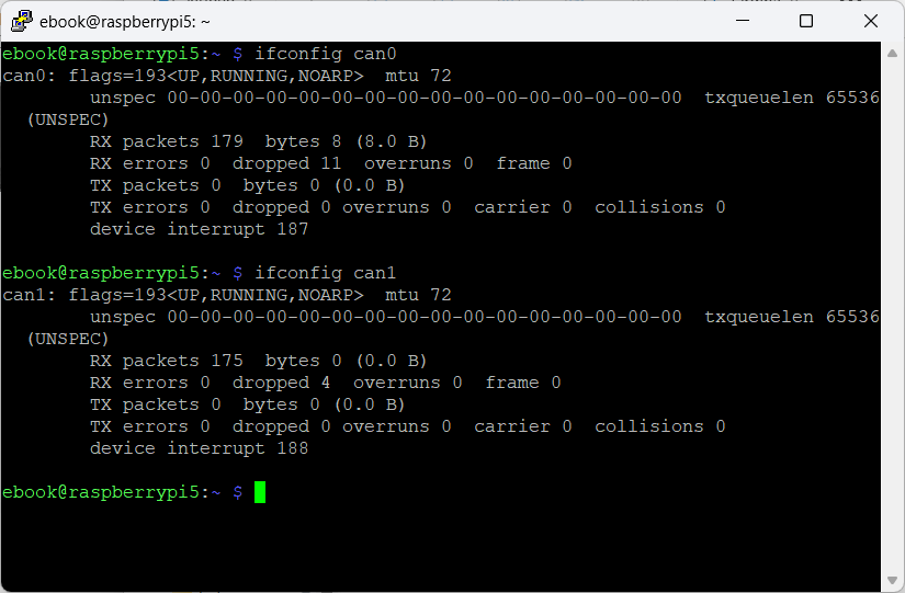
So the system is ready, then you can use standard canbus command to use the peripheral:
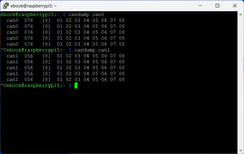
candump can0 -> to monitoring can bus traffic
cansend can0 7DF#0201050000000000 -> to send canbus commands
candump can1 -> to monitoring can bus traffic
Leave a Reply