EtherCAT® Shield for Raspberry PI – EtherC V1.6
EtherCAT® is an Ethernet-based fieldbus system, invented by Beckhoff Automation. The protocol is standardized in IEC 61158 and is suitable for both hard and soft real-time requirements in automation technology. EtherC V 1.6 is an extension board for RaspBerry Pi based on LAN9252 EtherCAT® Slave produced by Microchip, there is a Real Time clock powered by a 12 mm battery CR1216 (Battery is not included). The LAN9252 is a 2/3-port EtherCAT® slave controller wi th integrated dual Ethernet PHYs Which Contain each to full-duplex 100BASE-TX transceiver and support 100Mbps (100 BASE-TX) operation. Three possible configurations are possible: Microcontroller Mode, Digital I / O and Expansion Mode.
Our board not implements a fusion between the Microcontroller mode and the Digital I/O.
Raspberry Boards Compatibility
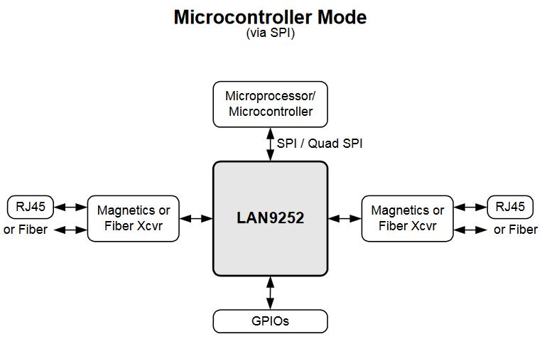
The SPI bus permits the communication with Raspberry PI, while the GPIO of LAN9252 are not exported. These pins are controlled by EtherCAT bus, no from Raspberry GPIO.
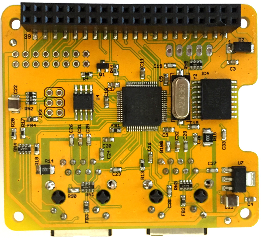
EtherC V 1.6 Bottom View
On pin header JP2 are exported the following RPI pins :
- GPIO05
- GPIO06
- GPIO12
- GPIO13
- GPIO16
- GPIO19
- GPIO20
- GPIO21
- GPIO22
- GPIO23
- GPIO24
- GPIO26
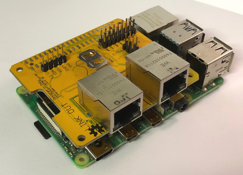
EtherCAT on Raspberry Pi 4
Every EtherCAT® slave requires a Vendor ID, we use the ID of SG Electronic Systems. This company supports us with boards distribution and their customization.
It’s possible to order this board on our Shop.
SOFTWARE CONFIGURATION
INSTALLATION ETHERBERRY TO RASPBERRY
- Download the EtherC Code: EtherC_Code_v1.6
- Copy EtherC_Code_v1.6 to Raspberry
- Read Instructions.txt in EtherC_Code_v1.6 directory use the example code.
- With the example code provided, it is possible to configure the IO in JP2 as Inputs or Outputs, and read the Inputs and set the Outputs via Ethercat.
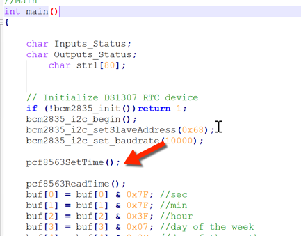
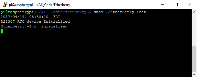
- It is possible to Read the i2c RTC (DS3231) via ETHERCAT® . EtherC_Test.cpp is only an example that initialize the RTC at the same value “14 April 2017”, if you want to set the RTC with a different value, you must remove the line marked in the picture below.
For further applications it is possible add device i2c in EtherC header JP1 and control via ETHERCAT®: EtherC XML Configuration ETHERCAT® (ESI)
CONFIGURATION DEMO ETHERCAT® MASTER WITH CODESYS Development System V3
Dowloand EtherC XML for configuration slave on ETHERCAT® master: EtherC_XML_v1.6
Download and install CODESYS Development System V3 from: http://store.codesys.com/codesys.html
Download and install WinPcap from: https://www.winpcap.org/install/default.htm
Download Codesys project Demo_EtherC_Ethercat_Master_v1.6.zip
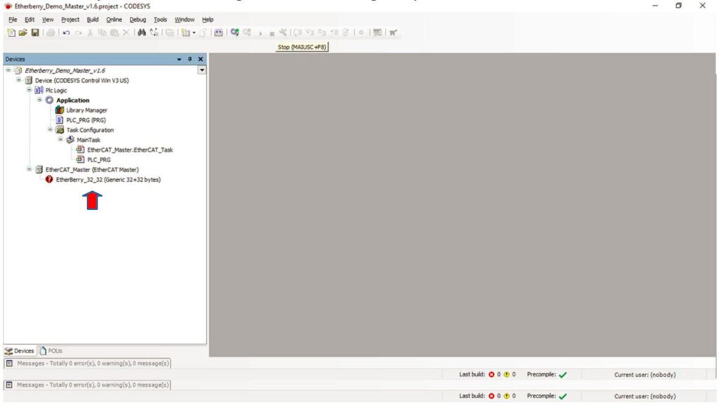
Unzip and open EtherC_Demo_Master_v1.6.project
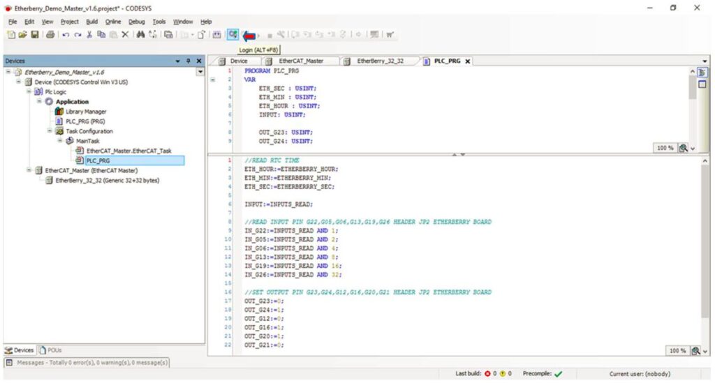
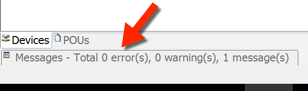
At first opening you see that our EtherC Ethercat slave is not installed (see the red arrow)
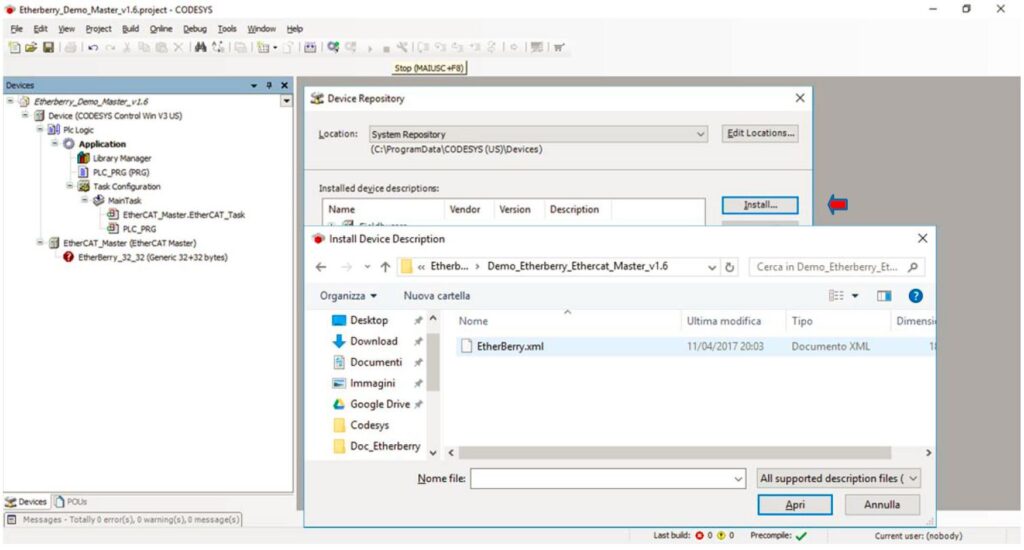
Install EtherC Ethercat slave clicking on Tools→Device Repository…
Click on Install.. (see red arrow) and select EtherC.xml located in Codesys project directory.
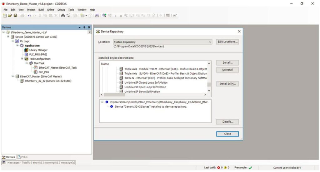
EtherC Salve is installed click Close
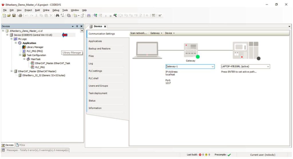
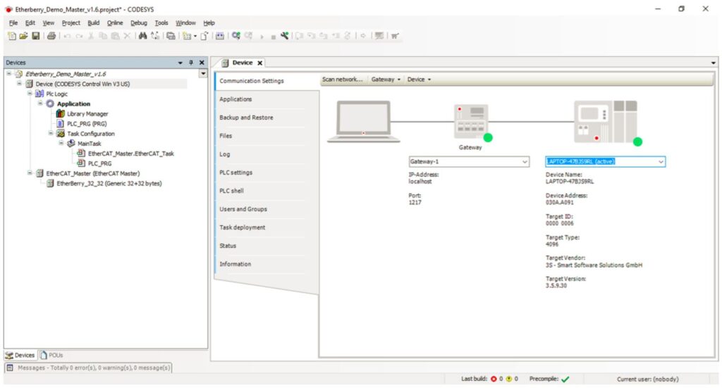
Double click on Device (see red Arrow) to open Device Tab.
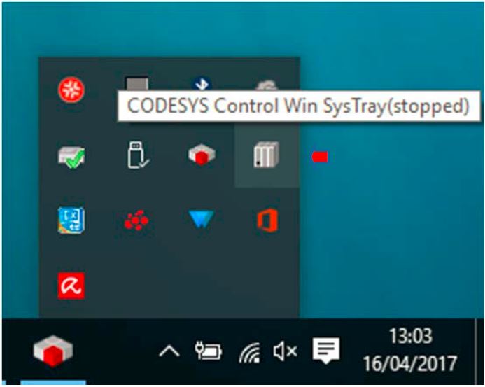
Click on Codesys Control Win sys (bottom right corner windows see red arrow)
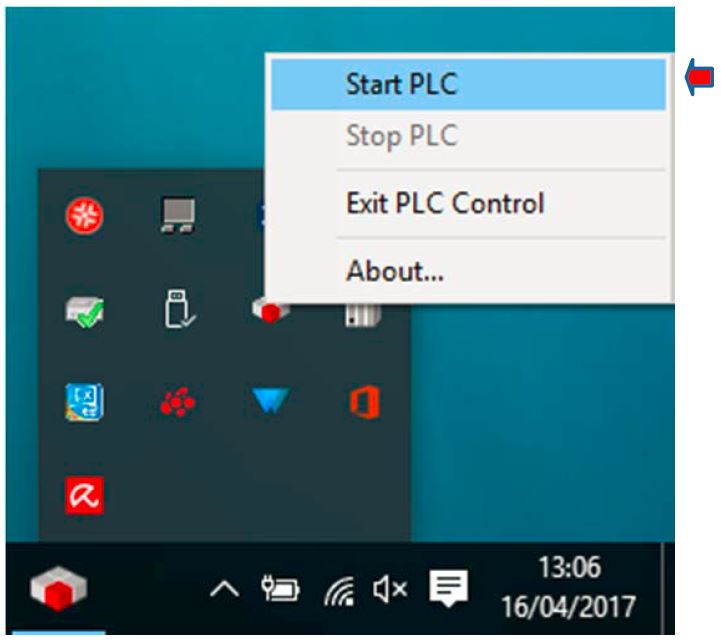
Start PLC
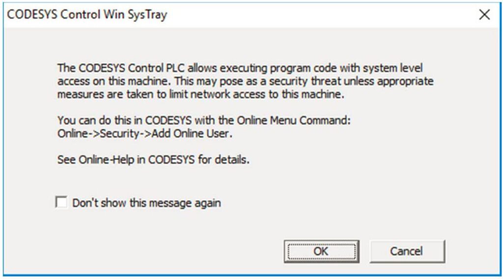
Click ok
In Codesys Project click in selection box (see red arrow) and Press Enter
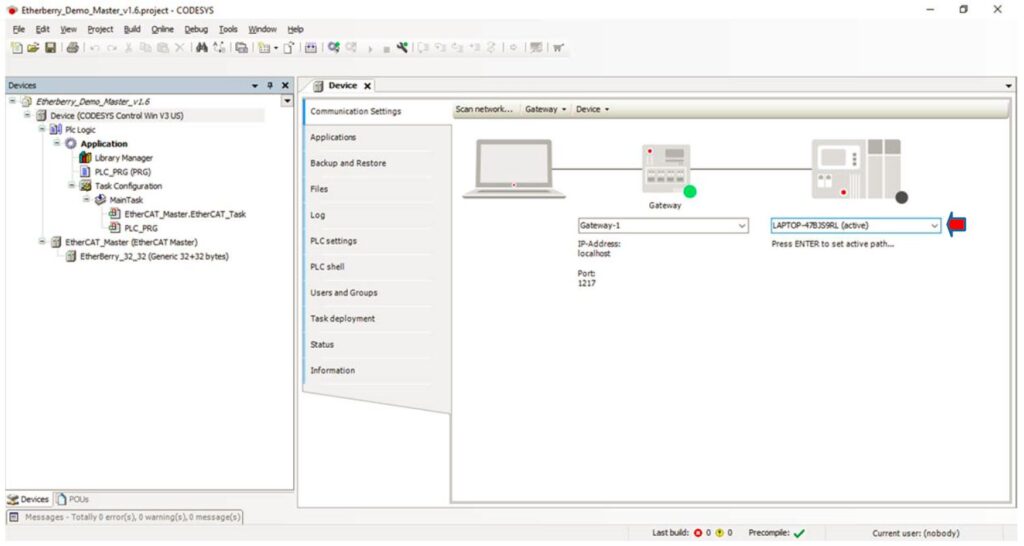
If everything is ok PLC will be connected.
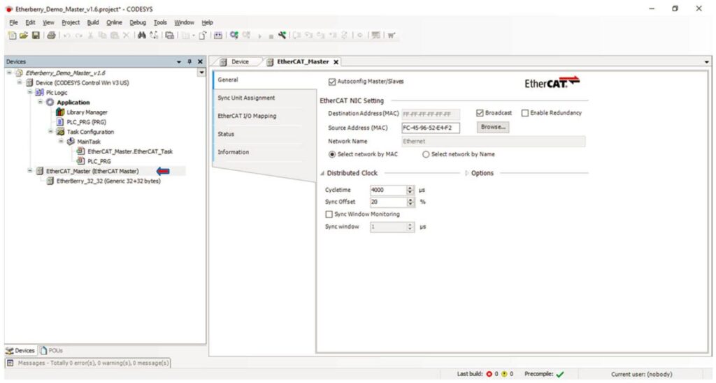
Double Click on EtherCAT_Master (see red arrow)
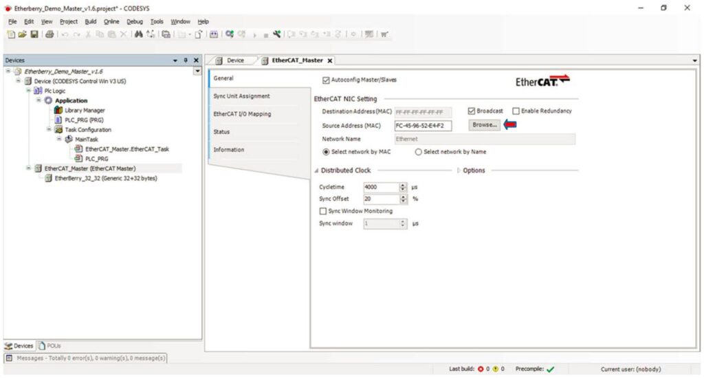
Click on Browse (see red arrow)
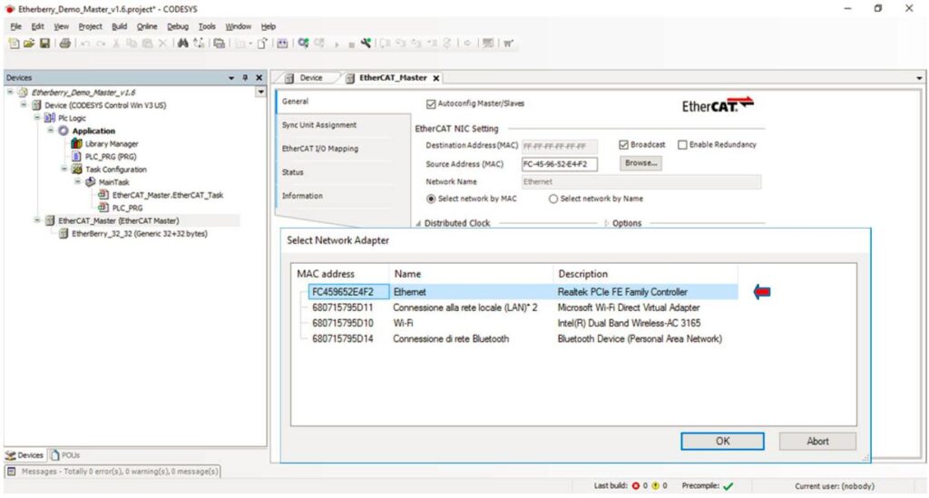
Select the MAC Address of your PC Ethernet Card (see red arrow) and click OK.
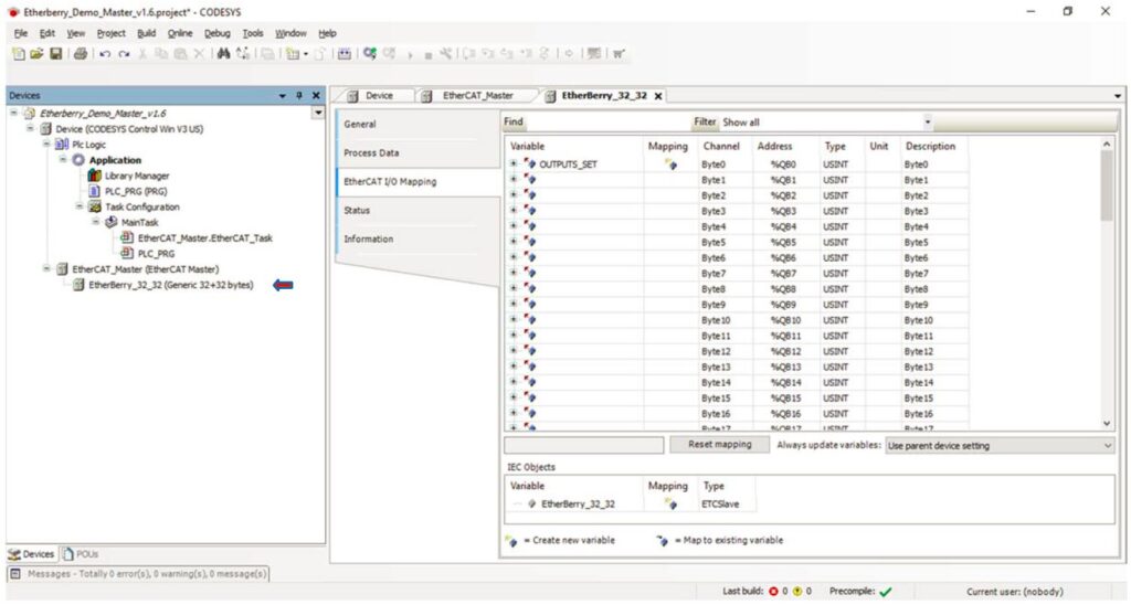
Double Click EtherC_32_32 (see red arrow) and click EtherCAT I/O Mapping, here are defined the variables associated to the I/O of EtherC slave. ( Don’t do anything to use demo project).
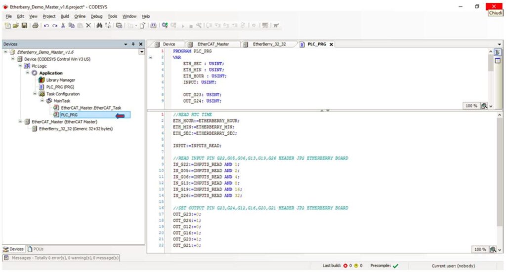
Double Click PLC_PRG(see red arrow) , this is the the code of the demo project. ( Don’t do anything to use demo project).
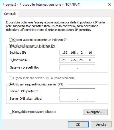
Set static IP in your PC Ethernet.
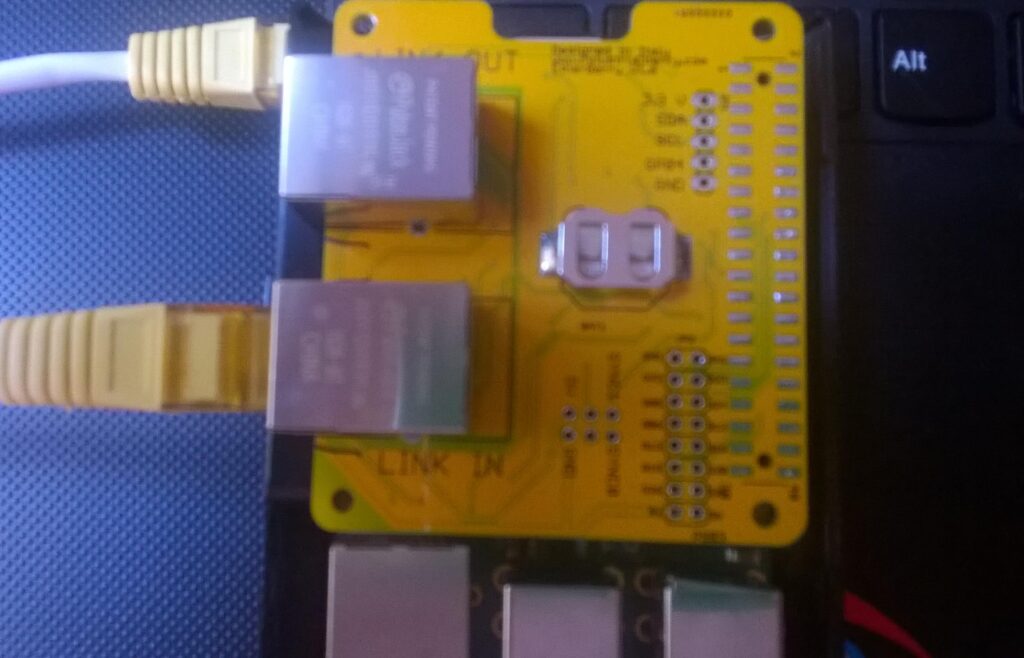
Connect network cable between your PC and EtherC Board (LINK_IN)
Run the EtherC from Raspberry (for more detail to compile the code see section Installation EtherC to Raspberry)
In Codesys Project click login (see red arrow).
Click Start (see red arrow)
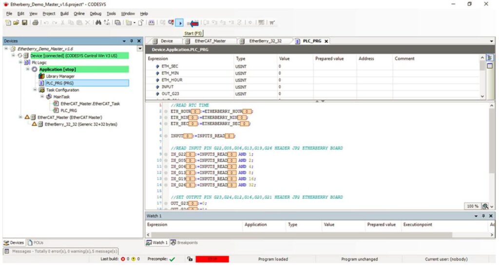
Master and Salve are connected and exchange the data
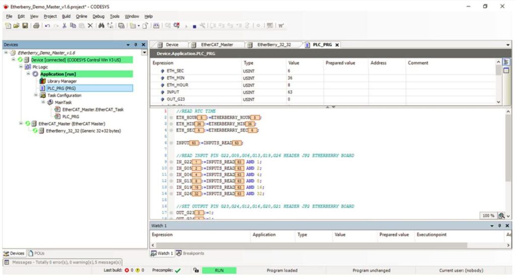
In the EtherC Board you can read the outputs G23,G24,G12,G16,G20,G21 HEADER JP2 or set the inputs G22,G05,G06,G13,G19,G26 HEADER JP2 EtherC and see the variables changing in the codesys project.
Update to CODESYS 3.5.12
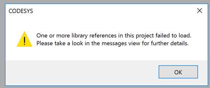
When using the Projekt with newer Codesys Version (tested with 3.5.12) you may have errors, when started Codesys.
First update the Project Environment, this screens appears automatically
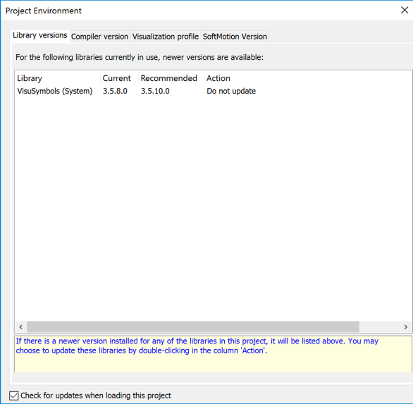
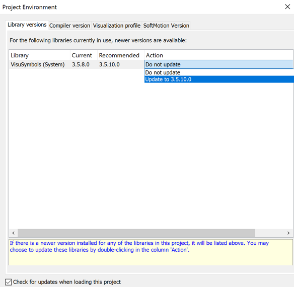
Select in all section the latest software, on Library versions select the 3.5.10.0
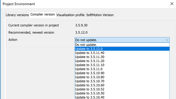
Now you can select the Compiler version update with 3.5.12
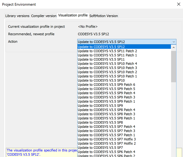
Now you can select the Visualization profile update with SP12
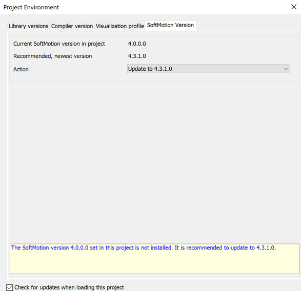
Now update the SoftMotion Version update
Now press ENTER, the Codesys updates the environment
But there is still something to do…
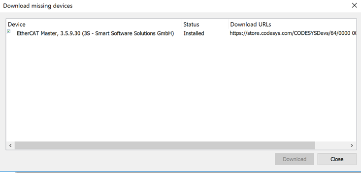
Download missing device description…
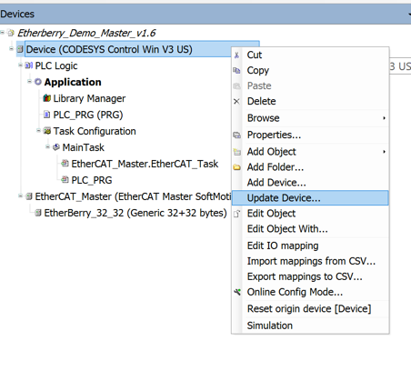
Right click on the devices…
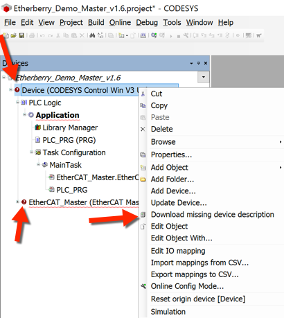
This will download the device description…
But there are still errors and again there is something to do..
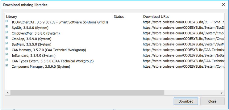
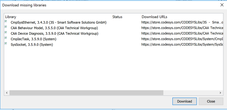
Upgrade the Library
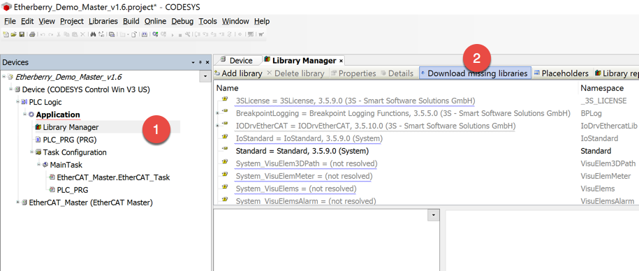
These are the modules that need an upgrade
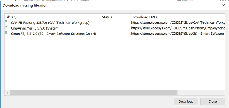
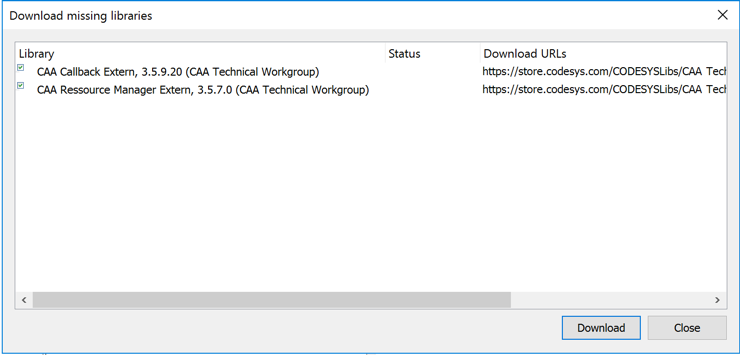
Finally there is no more “Download missing library” section..
Now we are ready and no more errors left..
Now you can proceed..
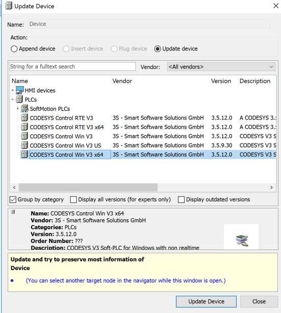
If you use Codesys Version for 64 Bit, than you have to change the device in the project, otherwise you can not connect to the PLC.
Follow the last two steps: Update Device
Select the CODESYS Control Win V3 x64
Leave a Reply