Relays Board V1.0.0
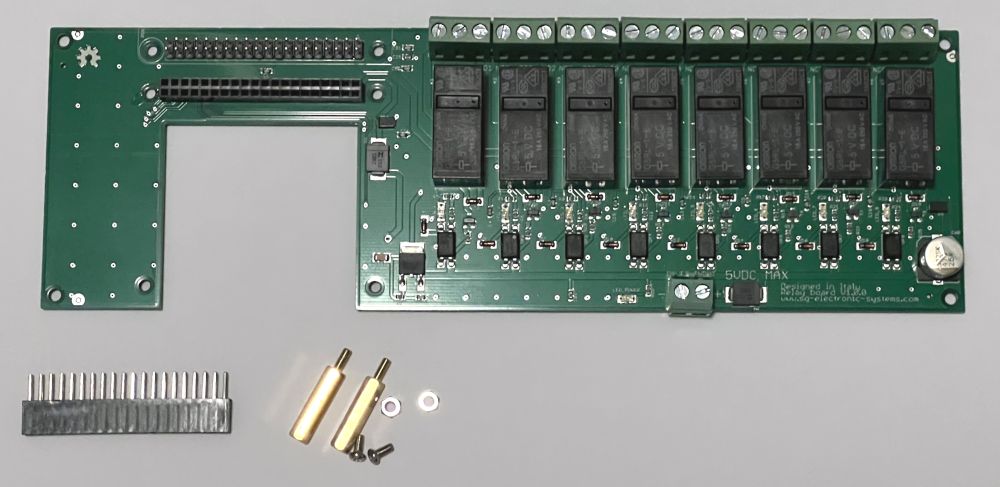
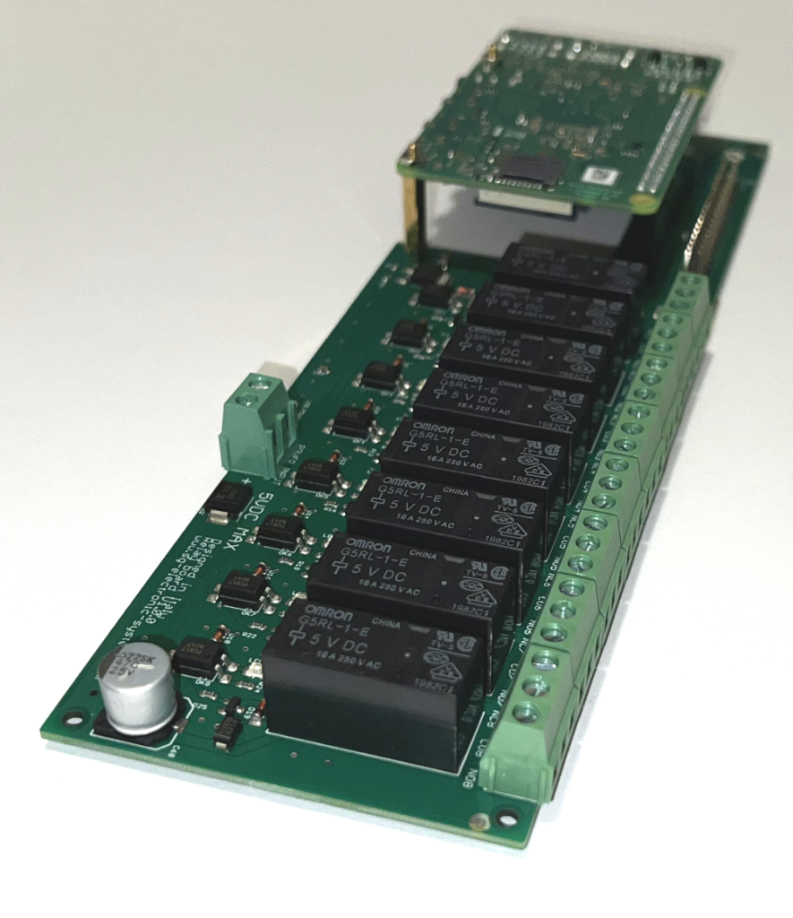
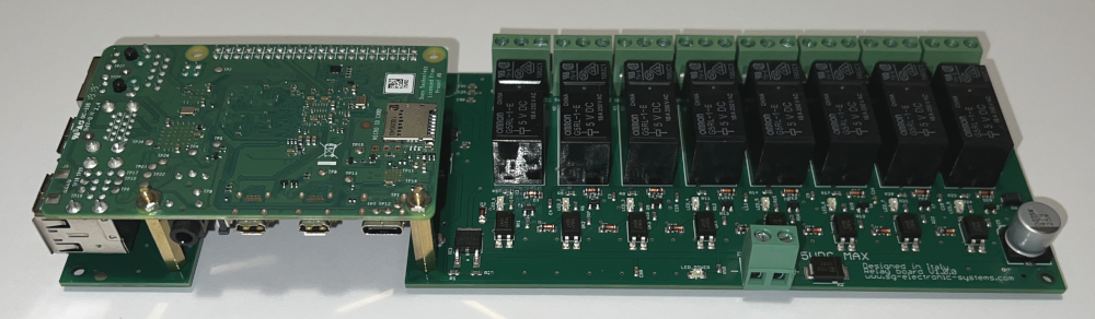
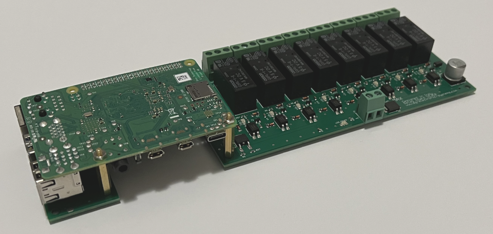
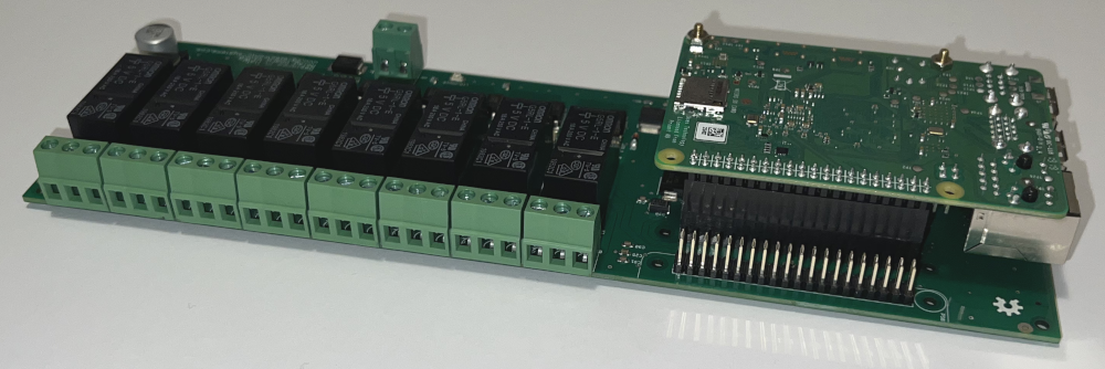
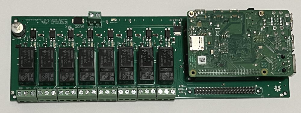
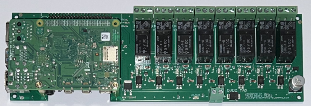
The Relay V1.0.0 is an expansion board with 8 relays controlled by Raspberry PI GPIO. With this board you are able to control 8 hi power relays Omron G5RL-1-E (16A 250V). Every relay has a dedicated status led. The power supply is provided from a terminal block (POWER INPUT 5V DC), with our kit you’ll receive the board, a 20×2 header and a couple of stand off for Raspberry PI installation. This project is open hardware as all our project, you are free to download schematic, gerber, cad file, bill of material and software scripts.
It’s possible to order this board on our Shop.
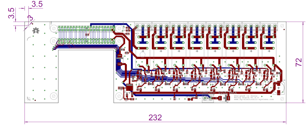
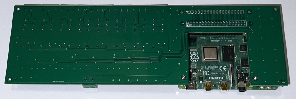
The dimensions are 232 x 72 mm with 4 fixing hole (3 mm), it is compliant with a classical DIN Rail PCB mount with an height of 72 mm.
Hardware
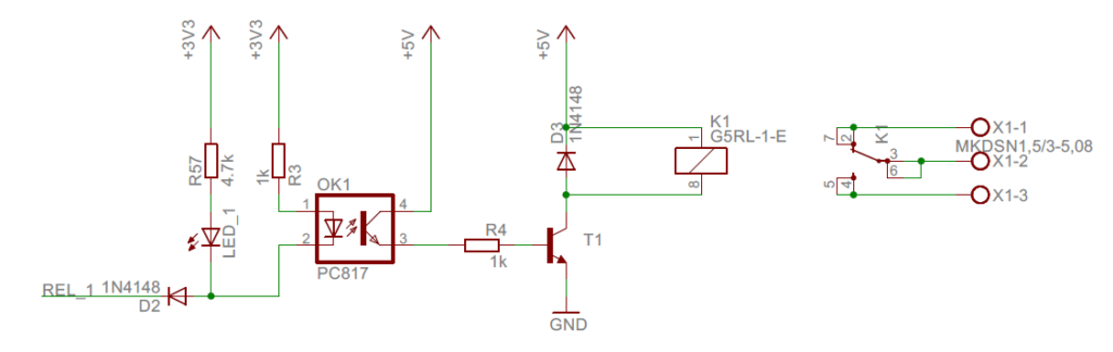
The 8 relays are controlled directly from Raspberry GPIO thought an optocoupler, see the following image.
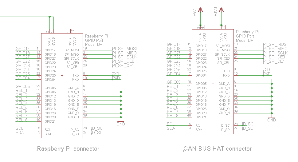
The correspondence between relay channels and Pi pins:
| Raspberry PI GPIO | Relay number |
| GPIO 06 | CHANNEL 1 |
| GPIO 12 | CHANNEL 2 |
| GPIO 13 | CHANNEL 3 |
| GPIO 19 | CHANNEL 4 |
| GPIO 16 | CHANNEL 5 |
| GPIO 26 | CHANNEL 6 |
| GPIO 20 | CHANNEL 7 |
| GPIO 21 | CHANNEL 8 |
The selected relay G5RL has the following configuration 1 Form C (SPDT-NO, NC)

WARNING For your safety don’t use this board with high voltage
The are two 20×2 pins connectors, one for Raspberry Pi and the other for our Dual Can Bus board. In this way it is possible to control the Relay with CAN BUS.
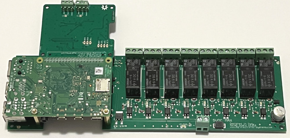
The main power supply (5V DC) is provided from an external power supply thought connector POWER INPUT. The LED_POWER signals the presence of external power.
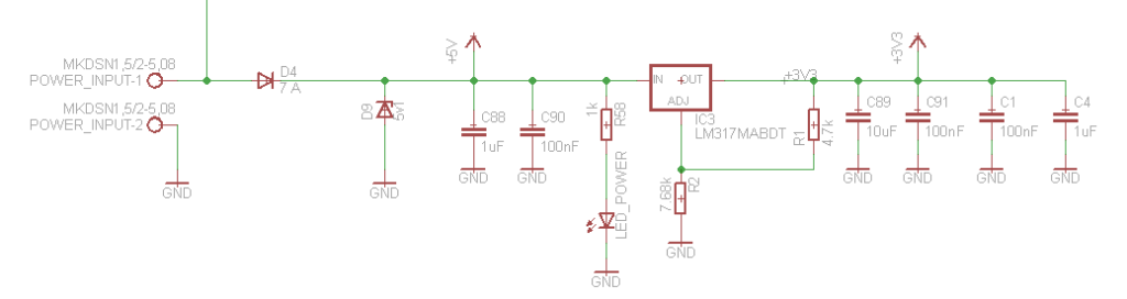
The first couple (D4 and D9) is used to protect Relays circuits and external CAN BUS board, the second (D1 and D20) is used for Raspberry Pi.
Schematic PDF
Layout PDF
Gerber Files
CAD Files
BOM and CPL
Software
The GPIOs control on Raspberry PI is very simple, there are different software libraries, the most famous are WiringPi and Python. On our demo we use Python, all our scripts are ready for download.
sudo apt-get update
sudo apt-get install python3-pip
sudo pip3 install RPi.GPIO
Relay 1 is connected to GPIO 6 and the Python script to switch on it is
import RPi.GPIO as GPIO
import time
GPIO.setmode(GPIO.BCM)
GPIO.setwarnings(False)
GPIO.setup(6,GPIO.OUT)
print("RELAY 1 on")
GPIO.output(6,GPIO.LOW)
Instead to set off Relay 1 the script is
import RPi.GPIO as GPIO
import time
GPIO.setmode(GPIO.BCM)
GPIO.setwarnings(False)
GPIO.setup(6,GPIO.OUT)
print("RELAY 1 off")
GPIO.output(6,GPIO.HIGH)
Leave a Reply