Dual Level Sensor V1.2
The board is a level sensor equipped with a couple of VL53L0X ( a new generation Time-of-Flight ToF). The Laser-ranging module provides accurate distance measurement whatever the target reflectances unlike conventional
technologies. It can measure absolute distances up to 2m. The sensor is a Class 1 laser device compliant with latest
standard IEC 60825-1:2014 – 3rd edition.
The heart of this board is the classica MCU ATmega328P programmed with Arduino bootloader. We have selected the Arduino Nano MCU, because this board is totally open hardware, you are free to download CAD File and firmware sketch.
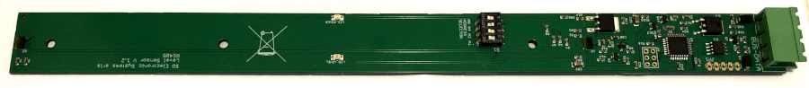
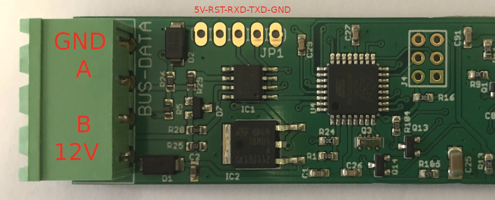
The main connection is the green connector 4 way with pitch 5,08mm, for power supply and RS485 communication.
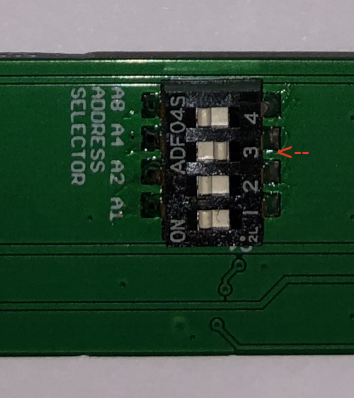
For example the following configuration set the address 4 + ADDRESS_OFFSET (0x28) =0x2C
Programming
Download the following arduino sketch
VL53L0X_Dual_ReadDistance_V1.2.ino
For board programming we have select a classical AVR ISP STK500 produced by Seeedstudio. The grey wire must be connected to header J4, instead the power supply (12V) to green connector.
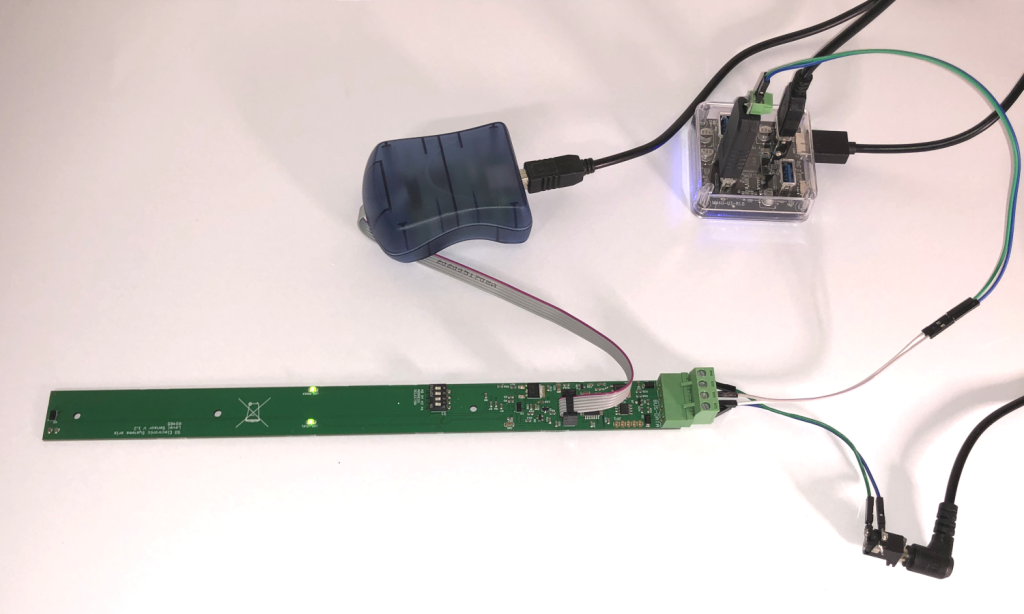
Connectors details
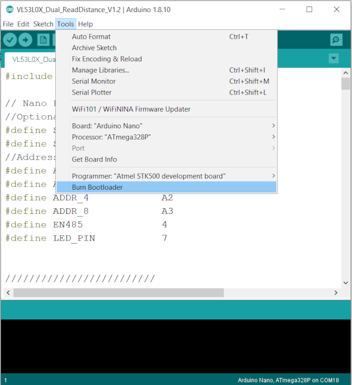
All our boards are programmed in factory, but if you want to update the Bootloader follow these steps:
- From Arduino IDE select Tools menu
- Select the board “Arduino Nano”
- Processor ATmega328P
- Port of programmer
- Programmer “Atmel STK500 development board”
- Connect the grey programmer wire to the connector J4
- Connect the 12V to green connector
- Click on Burn Bootloader
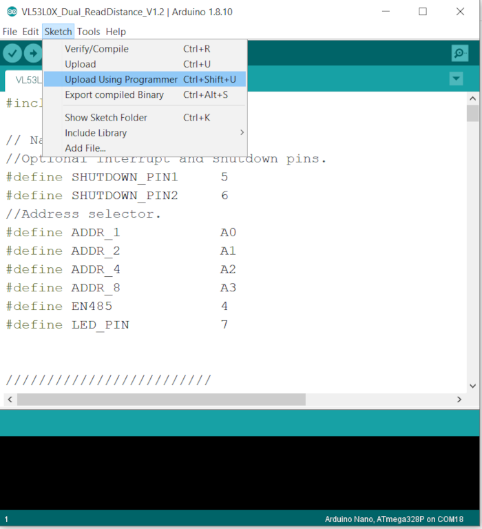
If you want to update or modify the sketch follow these steps:
- From Arduino IDE menu select Sketch
- Upload Using Programmer
Our firmware is based on Seeedstudios library “Seeed_vl53l0x.h“
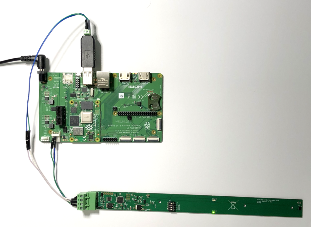
Software control
The board connection require an RS485 interface, for our test we also used the original CM4 carrier board, because we have already the 12V for power. If you use a different board, or a PC you must to use an external power supply.
For our test on Windows PC we have used RealTerm, the baud rate is fixed at 9600, the other parameters are 8N1.
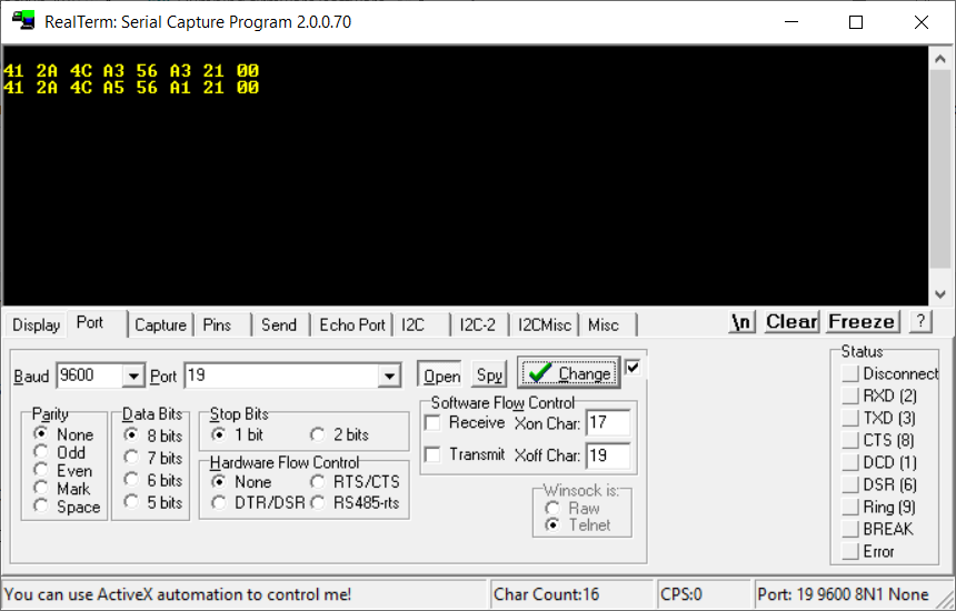
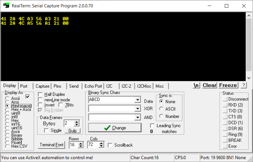
The visualization is Hex format
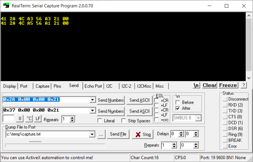
The command for reading is a fixed length message composed by
SLAVE_ADDRESS 0x00 0x00 ‘!’
The sensor board answers only if reads its address on the bus. In the following example the address selector is set to 2, considering the OFFSET_ADDRESS (0x28) we have 0x2A for address.
The command is 0x2A 0x00 0x00 0x21, click on Send Number
The answer is composed by the following data:
- 0x41 ‘A’
- 0x2A Slave address
- 0x4C ‘L’
- Level 1
- 0x56 ‘V’
- Level 2
- 0x21 ‘!’
- 0x00
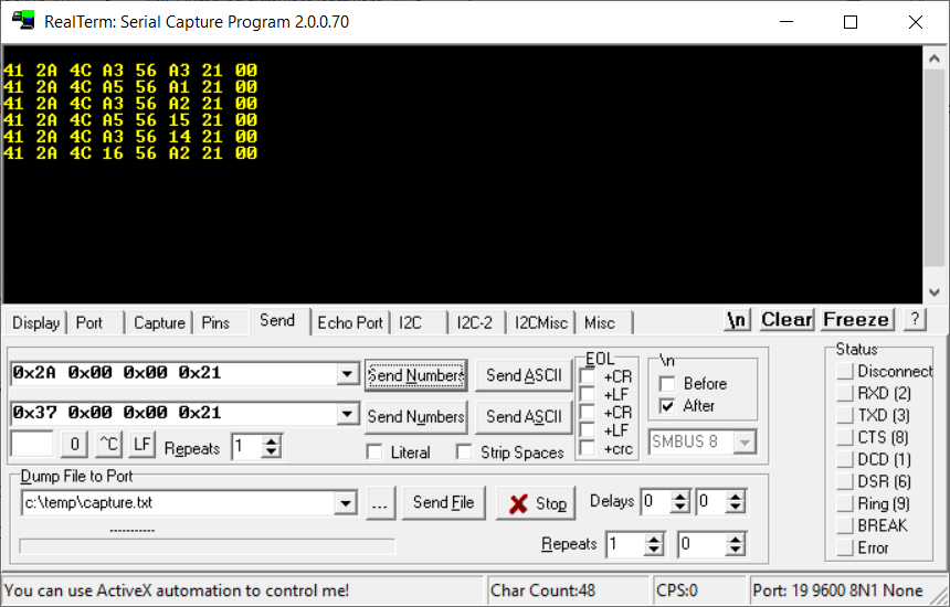
Sensor 1 is U1 and it is far from green connector, instead sensor 2 is U2 near green connector.
Leave a Reply