Dual Serial RS232 Shield for Raspberry Pi
DualSerial V2.2 is an extension board for RaspBerry Pi. It is an Open Hardware Design. It has two functionalities: a double RS232 interface and a 5V Fan. The central device of the board is the SC16IS752 an I2C-bus/SPI bus interface to a dual-channel high performance UART offering data rates up to 5 Mbit/s.
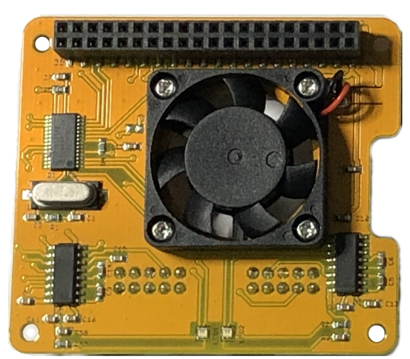
Dual Serial V2.2 Bottom view
DualSerial V 2.2 is composed by three blocks: a SPI-UART converter SC16IS752 and two UART-RS232 transceivers MAX3232.
SC16IS752 is a stand alone SPI/I2C dual uart controller full integrated in
linux kernel.
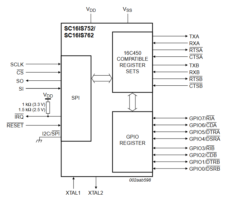
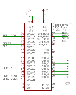
Considering that into the standard Raspberry ISO it is already present the overlay for SPI1, we ha connected the SC16IS752 to SPI1. At the start, the driver was implemented as a block device. It is supplied by 3.3V from raspberry connector. The complete board pinout is the follow:
• SPI1 CS0 is on GPIO18
• SPI1 MISO is on GPIO19
• SPI1 MOSI is on GPIO20
• SPI1 CLK is on GPIO21
• INTERRUPT is on GPIO24
• RESET (not connected) is on GPIO23
The pins IRQ and RST are active low and a pull-up resistor for each to Vcc
are mandatory. In order to control the RST pin with Raspberry it is necessary to solder a 0 resistor R6. The selected oscillator is a classical HC-49/US with a frequency of 14.7456MHZ. There are a couple of bi-color leds (each for port) in order to signal the serial activity.
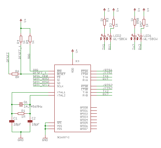
The RS232 side is implemented with a couple of MAX3232 of Texas Instruments. The MAX3232 device consists of two line drivers, two line receivers ,and a dual charge-pump circuit with ±15-kV ESD protection terminal to terminal. The device meets the requirements of TIA/EIA-232-F and provides the electrical interface between an asynchronous communication controller and the serial-port connector. Also the pins CTS and RTS are connected, in this way it is possible to use the hardware flow control of RS232.
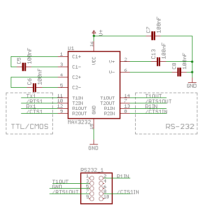
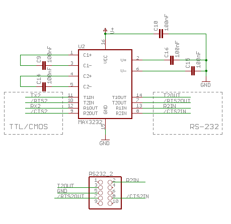
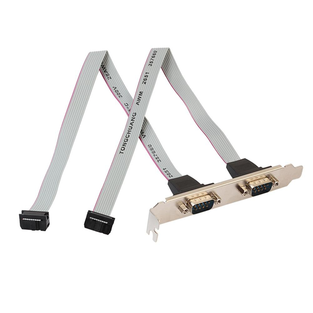
The standard RS232 DB9 connector requires a big amount of pcb ares, for
this reason we have use the classical 2×5 header pin connector used into all PC motherboard. With a standard flat cable it is simple to obtain the classical DB9 male connector
Software test
Download ready to use ISO from Raspberry official site.
After that write the SD card, when the writing procedure
is completed, to enable the driver ttySC0 and ttySC1 open the file
/boot/config.txt
and add the following line in Overlay section:
dtoverlay=sc16is752-spi1,int_pin=24
Save the file /boot/config.txt connect SD card to Raspberry and power on. If
you already have a ready OS in your Raspberry, open the file /boot/config.txt with the following command
sudo nano /boot/config.txt
add the overlay and reboot
sudo reboot
Connect via telnet with raspberry, to identify the name of can interface associated with the spi. Run the following command:
pi@raspberrypi ~ $ ls /dev/ttySC*
This is the output:
ttySC0
ttySC1
So the system is ready then you can use standard shell command to use the
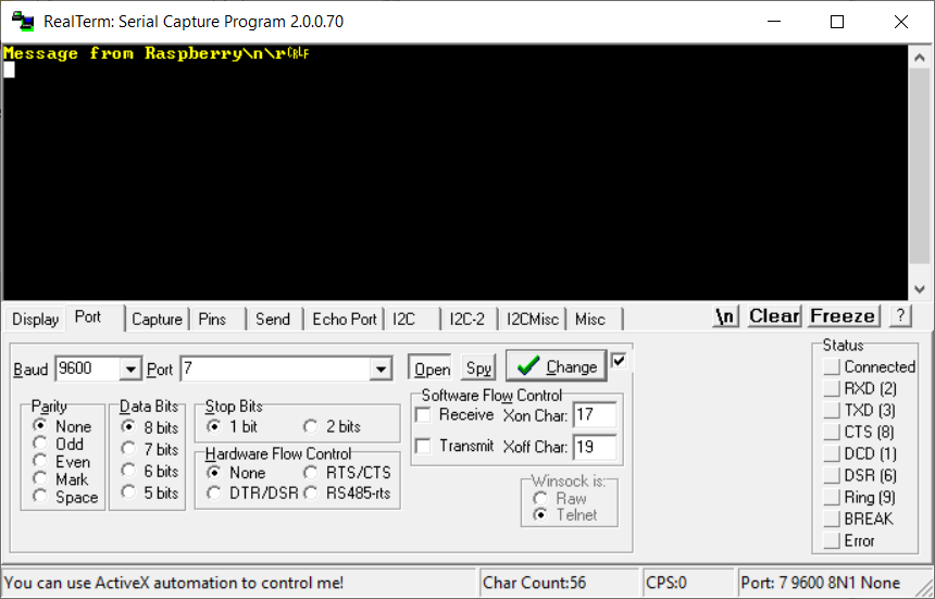
peripherals. On PC open your serial port with a program like Ralterm and use the following configuration: 9600 8N1.
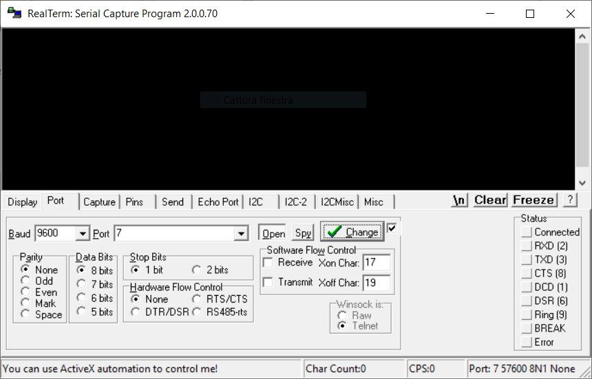
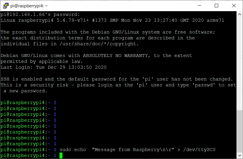
In order to send a message from ttySC0 to Realterm use the
following command
sudo echo “Message to send\n\r” > /dev/ttySC0
On Realterm, you can see the received message
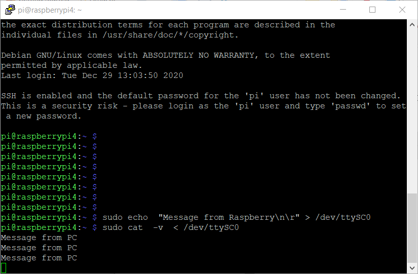
In order to send a message from Realterm to ttySC0 use the
following command
sudo cat -v < /dev/ttySC0
On Realterm, you can send the message with button send.
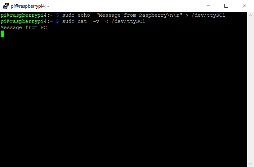
The same procedure is valid for the second serial port ttySC1
Leave a Reply