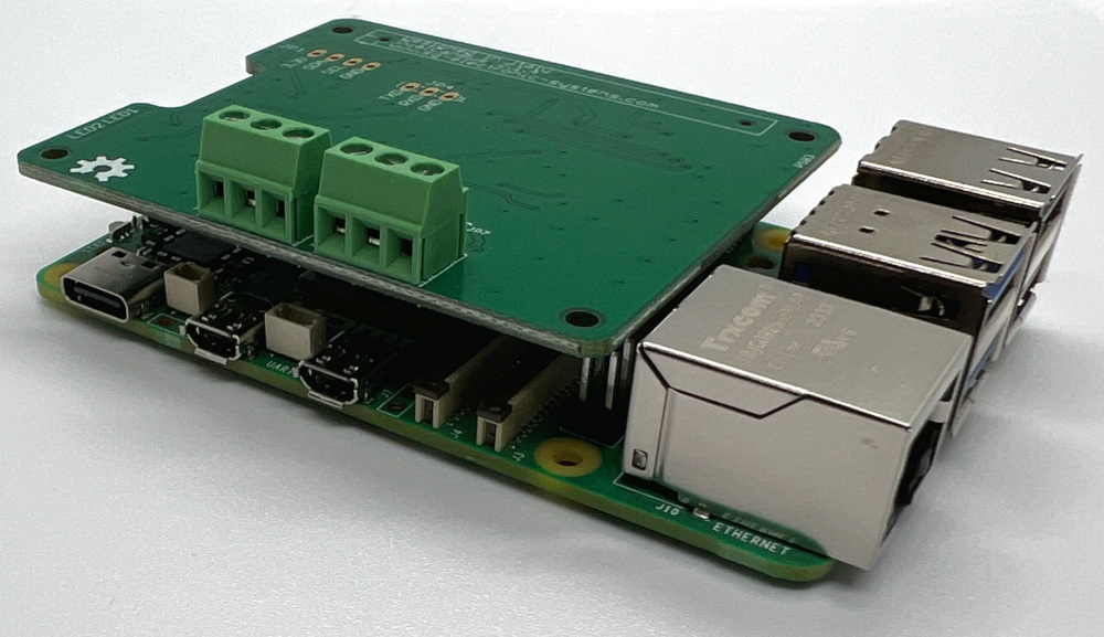
CAN BUS Dual Base V2.1.4 Shield for Raspberry
Can Bus Dual Base Pi V 2.1.4 (new version of is a CAN Can Bus Dual Pi V 2.1) BUS Shield for RaspBerry Pi. It is an Open Hardware Design. It has two functionalities: a can bus module and an onboard Real Time clock powered by a 12 mm battery CR1216 (Battery is not included). The CanBus is based on a couple of MCP2515 SPI controllers and MCP2557 transceivers. All functionalities are full integrated in standard linux kernel, so, they can be available on fly, or at last recompiling linux kernel to add can bus functionalities. The real time clock is based on PCF85063 I2C controller. This is the same RTC of official carrier CM4IO. It is full compatible with linux too. Using I2C Kernel module, and standard kernel functions, date and hour can be set/get by simple commands. On the bottom side is located an on board battery to guarantee a data autonomy. In chapter hardware there are all informations on principal components, schematics to rebuild and modify Raspberry PI board.
Raspberry Boards Compatibility
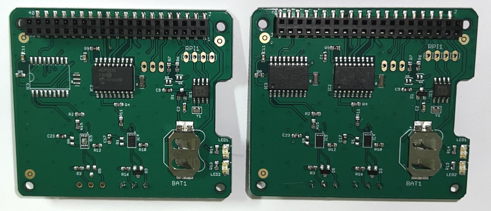
There are 3 main differences with previous model:
- the 40 pins connector is shorter than previus
- the old transceives MCP2551 have been replaced with newer MCP5557
- there is a new RTC PCF85063
It’s possible to order this board on our Shop.
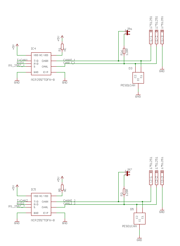
The RPI connector exposes two SPI slave select pins, SPI CE0 on pin 24 and SPI CE1 on pin 26. The first is used for MCP2515 channel 1 and the second for MCP2515 channel 2. The same situation is present for the interrupt pins, the first is connected on GPIO22 (pin 15) and the second on GPIO25 (pin 22).
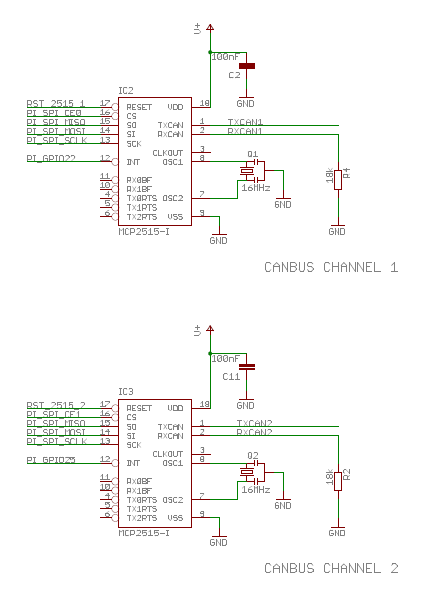
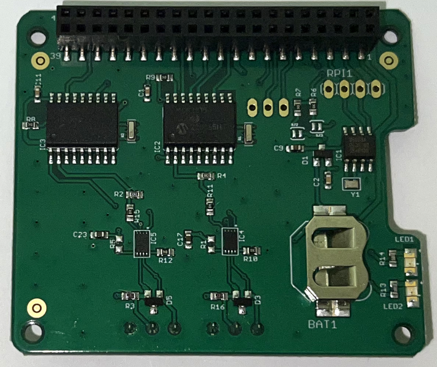
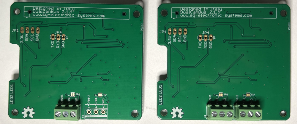
Can Bus Dual Base V 2.1.4 is composed by three blocks: a couple of CanBus transceiver Isolated and a Real Time Clock. MCP2515 is a stand alone SPI canbus controller full integrated in linux kernel. At the start, the driver was implemented as a block device. Recently it is assumed to be a network module into the kernel. It is supplied by 3.3V from raspberry connector. MCP5557 is supplied by 5V from Raspberry connector instead. So, to match voltage physical level between the two chips, a voltage matching made by R4 and RN4 has been used. There are two SMD Jumpers, JP6 for CAN Bus Channel 1 and JP7 for CAN Bus Channel 2, these jumpers provide the 120 ohm termination for the first and the last device.
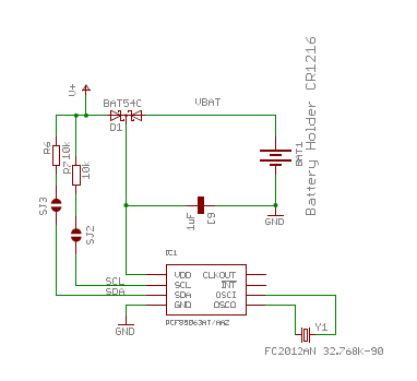
The old RTC DS3231 has been replaced due to component shortage with the PCF85063, it has the following I2C address 0x51. The new RTC is the same of official Raspberry carried CM4IO, if you want to use our board on CM4IO remember to cut trace on SJ2 and SJ3.
Board installation
It is possible to install all our boards both on Raspberry Pi or CM4IO carrier, but it’s always suggested to use standoff M2.5 x 10 mm
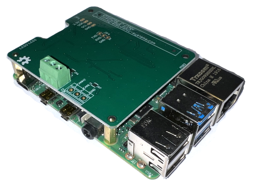
Dual Can Bus V2.1.4 on Raspberry Pi 5
It’s possible to insert the Raspberry with our Can Bus Board into a Phoenix din enclosure (RPI-BC 107,6 DEV-KIT KMGY – 2202874).
PDF Schematich
Board CAD File
Single channel Board BOM
Double channel Board BOM
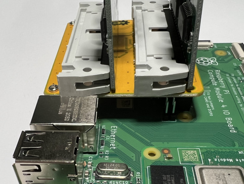
QUAD CAN ADAPTER INSTALLATION
Considering that the new Can Bus Dual has a shorter black connector, it is fundamental to fit completely the board inside the gray connector.
How to prepare a SD Card with CAN kernel modules (only for expert Linux users).
Prior to Bookworm, Raspberry Pi OS stored the boot partition at /boot/. Since Bookworm, the boot partition is located at /boot/firmware/
Edit /boot/firmware/config.txt modify the following row
dtoverlay=mcp2515-can0,oscillator=16000000,interrupt=22
dtoverlay=mcp2515-can1,oscillator=16000000,interrupt=25
Run the following command:
pi@raspberrypi ~ $ dmesg | grep -i can
This is the output:
[ 13.197388] CAN device driver interface
[ 15.375846] mcp251x spi0.0 can1: bit-timing not yet defined
[ 15.382408] mcp251x spi0.1 can0: bit-timing not yet defined
From the output it is possible to observe that can0 is associated to spi0.1 and can1 to spi0.0.
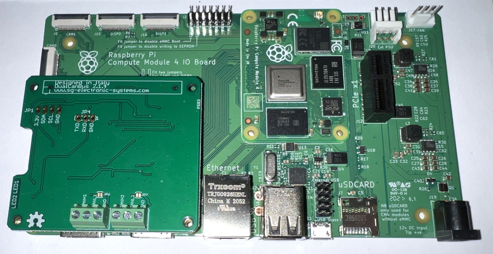
Respect the board shown in figure 1 the interface can0 is located in SPI0.1(X2 connector) and can1 in SPI0.0(X1 connector).
After your raspberry has been booted, go to home directory:
cd /home/pi/
nano can-start.sh
add these lines to the script
#!/bin/sh
#Can
ip link set can0 up type can bitrate 1000000
ip link set can1 up type can bitrate 1000000
Run the script:
sudo sh can-start.sh
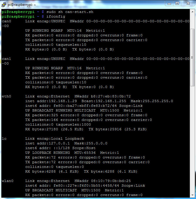
So the system is ready, then you can use standard canbus command to use the peripheral:
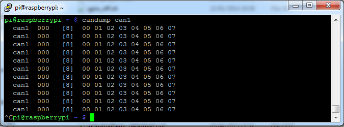
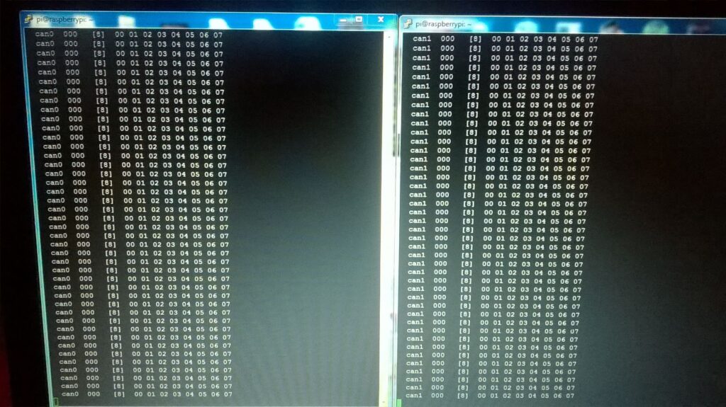
candump can0 -> to monitoring can bus traffic
cansend can0 7DF#0201050000000000 -> to send canbus commands
candump can1 -> to monitoring can bus traffic
cansend can1 7DF#0201050000000000 -> to send canbus commands
To use both interface simultaneously open 2 different telnet sessions.
Leave a Reply